Suture device

Inactive Publication Date: 2009-10-15
OLYMPUS MEDICAL SYST CORP
View PDF3 Cites 8 Cited by
  • Summary
  • Abstract
  • Description
  • Claims
  • Application Information

AI Technical Summary

Benefits of technology

[0008]The present invention has been made in light of the foregoing circumstances, and its object

Problems solved by technology

However, with respect to the suture device recorded in International Unexamined Patent Application, First Publication No. 2007-37326, when ejecting the anchors, it may happen that the rear end of the anchor catches on the edge of the needle, and is not able to be smoothly e

Method used


Image

  • Suture device
  • Suture device
  • Suture device

Examples


Embodiment Construction

[0026]Hereinbelow, the suture device of one embodiment of the present invention shall be described with reference to FIG. 1 to FIG. 15B.

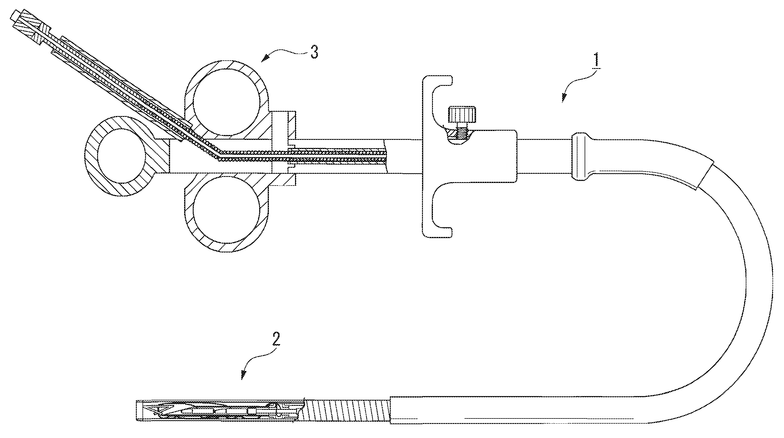
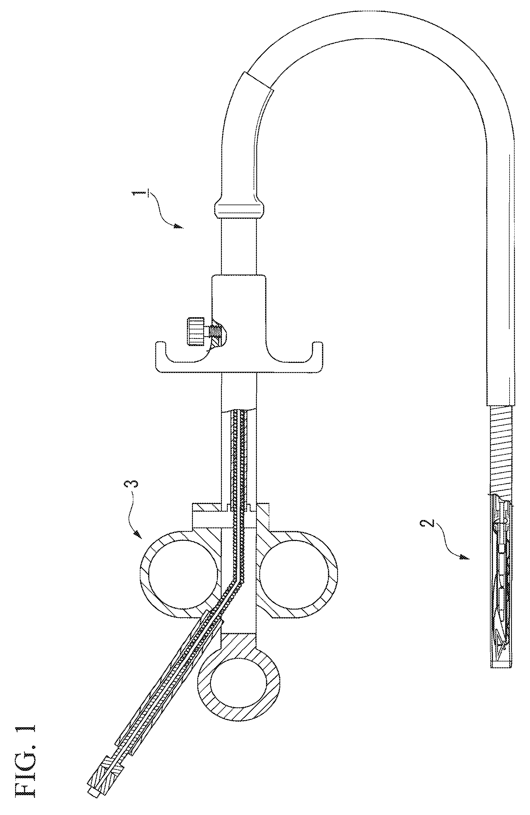
[0027]FIG. 1 is a figure which shows a suture device 1 of this embodiment. As shown in FIG. 1, the suture device 1 is provided and configured with a distal end portion 2 inserted into the body and an operating portion 3 for manipulating the respective mechanisms of the distal end portion 2.

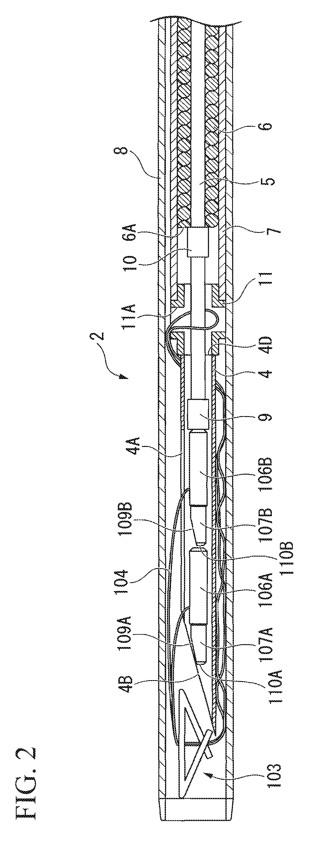
[0028]FIG. 2 is an enlarged view which shows a partial section of the distal end portion 2. The distal end portion 2 is provided and configured with a needle (distal member) 4 to which the below-mentioned suture unit is attached, a wire 5 which runs through the needle 4, a second sheath (parallel member) 6 through which runs the proximal end of the wire 5, a tube 7 through which the wire 5 and second sheath 6 are inserted in the axial direction with free retraction and advancement, and which is integrally fixed to the needle 4 on the proximal side of the needle 4,...


PUM


Abstract

A suture device which sutures tissue using a suture unit having a first anchor and a second anchor respectively attached to both ends of a suture thread, wherein a hollow distal member is provided which houses said first anchor and second anchor, the end face of the distal side of said distal member is formed so as to constitute a first sharp angle with the axis of said distal member, the distal side of said second anchor is provided with a sloped face so as to constitute a second sharp angle with the axis of said second anchor which is an angle at or below said first sharp angle, and said first anchor and said second anchor are axially aligned and housed inside said distal member so that said second anchor is positioned on the proximal side.

Description

BACKGROUND OF THE INVENTION[0001]1. Field of the Invention[0002]The present invention relates to a suture device that is inserted into a body cavity for use, and more particularly to a suture device employed when suturing perforations and the like which have formed in hollow organs such as the stomach, intestine or the like using suture thread which has anchors attached to both ends.[0003]2. Description of Related Art[0004]Heretofore, suture devices have been known which use suture thread having anchors attached to both ends for the purpose of suturing perforations, lacerations and the like which have formed in hollow organs such as the stomach, intestine or the like (e.g., see International Unexamined Patent Application, First Publication No. 2007-37326). With this suture device, suturing is conducted by having the anchors at both ends of the suture thread engage with tissue near the perforation at the interior or exterior of the tissue, and by drawing together the tissue engaged b...

Claims


Application Information

Patent Timeline
IPC IPC(8): A61B17/04
CPCA61B17/0469A61B17/0487A61B2017/0464A61B2017/0417A61B2017/0409
Inventor SHIONO, JUNJIHAYASHI, KENSUKESUZUKI, TAKAYUKI
Owner OLYMPUS MEDICAL SYST CORP
Why Eureka
Try Eureka