Slot-in disk drive device and method

a disk drive and slot-in technology, applied in the direction of data recording, instruments, disposition/mounting of heads, etc., can solve the problems of disc and disk drive devices that cannot be embedded with spindle motors of different sizes, device faults, disc and disk drive devices tend to be damaged, etc., to enhance the reliability of optical drive operation

Inactive Publication Date: 2008-02-28
QUANTA STORAGE INC
View PDF8 Cites 8 Cited by
  • Summary
  • Abstract
  • Description
  • Claims
  • Application Information

AI Technical Summary

Benefits of technology

[0008]The invention is directed to a slot-in disk drive device and a method thereof, wherein sizes of loaded discs are mechanically determined according to different moving properties of the discs, and the determination is further made according to the order of actuating sensing units so that the reliability of the operation of the optical drive is enhanced.
[0009]The invention is also directed to a disk drive device and a method thereof, wherein a simple link transmission mechanism is adopted to drive an ejecting bar to eject the disc so that the structure of the disk drive device is simplified and the cost thereof is reduced.
[0010]The invention is further directed to a disk drive device and a method thereof, wherein a guiding slot is extended to cause a loading stick to move alongside when the disc is being ejected so that the disc may be ejected more smoothly.

Problems solved by technology

However, different sizes of discs cannot be embedded with a spindle motor for rotating the disc correctly until the disc reach a playing position in the disk drive device without error, or otherwise the optical disc is jammed in the disk drive device.
Thus, the device tends to have a fault, or even the disc and the disk drive device tend to be damaged.
However, the guiding rod and the bar-linkage mechanism have to successively guide the disc to be aligned with the spindle motor, and the loading / ejecting mechanism is too complicated.
Also, the disc cannot be always kept horizontal via the peripheral point contacting to guide the disc.
Thus, when the foreign object or disc is being loaded, other switches corresponding to other sizes of discs may be touched and the determination error of the disc size may occur to cause the malfunction of the transmission mechanism and thus to cause the disk drive device to breakdown.
Thus, the conventional apparatus and method of the slot-in disk drive device for loading and ejecting the disc still have problems to be solved.

Method used


Image

  • Slot-in disk drive device and method
  • Slot-in disk drive device and method
  • Slot-in disk drive device and method

Examples


Embodiment Construction

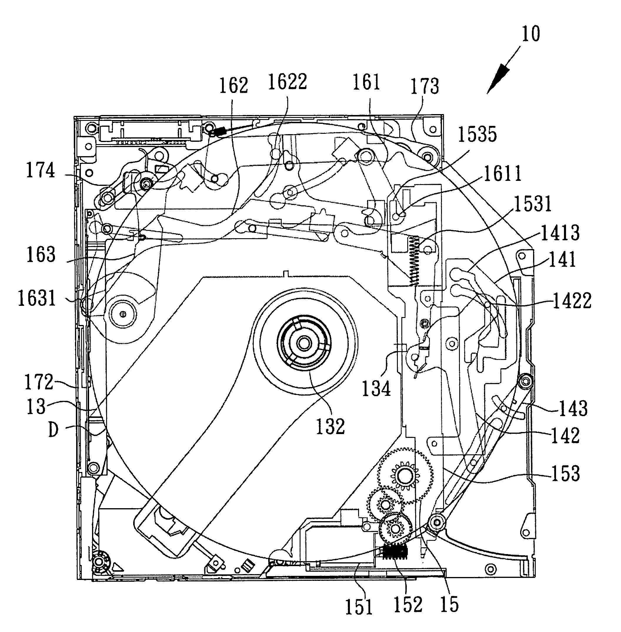
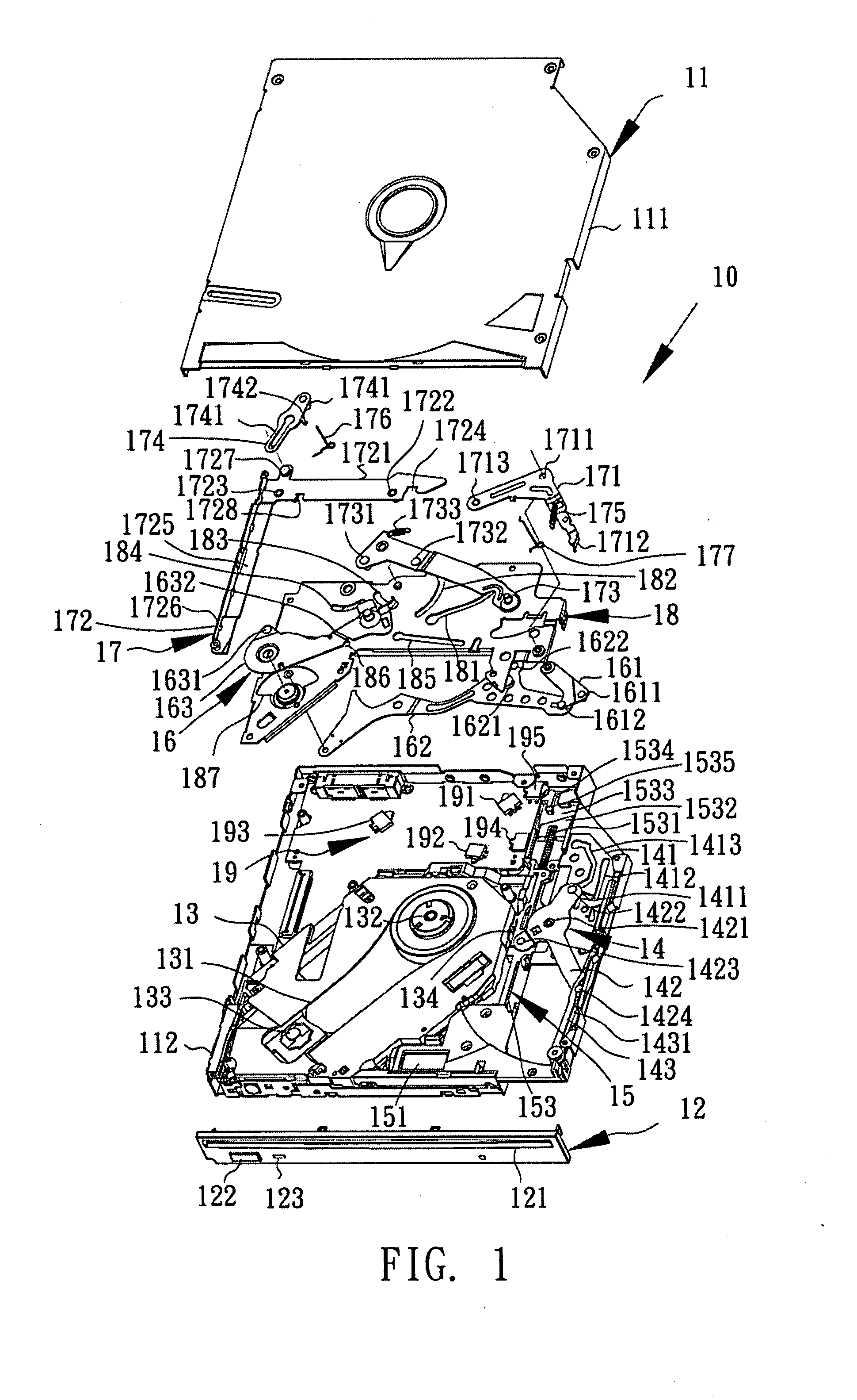
[0029]FIG. 1 is an exploded view showing components of a slot-in disk drive device according to the invention. Referring to FIG. 1, a slot-in disk drive device 10 of the invention includes a casing 11, a panel 12, a traverse 13, a loading unit 14, a drive unit 15, an ejecting unit 16, a receiving unit 17, a substrate 18 and a sensing unit 19. The ejecting unit 16 and the receiving unit 17 actuate the sensing unit 19 to sense a disc D (see FIG. 4) inserted into the disk drive device 10, and enable the drive unit 15 to move the loading unit 14 to push the disc D into the disk drive device 10, and further move the receiving unit 17 to guide the disc D to a predetermined position. Then, the traverse 13 rises to embed with the disc, rotates the disc D and then plays the disc or ejects the disc.

[0030]The casing 11 is composed of an upper case 111 and a lower case 112, which cover a hollow space for accommodating a disc drive mechanism for driving the disc D into and out of the casing 11. ...


PUM

PropertyMeasurementUnit
diameteraaaaaaaaaa
diameteraaaaaaaaaa
poweraaaaaaaaaa

Abstract

A slot-in disk drive device and a method thereof. The device includes a drive unit for providing power to move a slider. A loading unit moving with the slider drives a loading stick to push a disc into the device. The slider has a sliding slot. An ejecting unit with a bar-linkage mechanism has one end driven by the sliding slot, and the other end for rotating an ejecting bar to guide or push the disc out. A receiving unit has a receiving bar for guiding the disc, and has a positioning bar disposed between the loading unit and the ejecting unit. A sensing unit includes a plurality of sensing switches respectively disposed near the moving paths of the receiving bar, the ejecting unit and the positioning bar. The drive unit is enabled to load the disk is determined according to the order of actuating the switches.

Description

[0001]This application claims the benefit of Taiwan application Ser. No. 95131271, filed Aug. 24, 2006, the subject matter of which is incorporated herein by reference.BACKGROUND OF THE INVENTION[0002]1. Field of the Invention[0003]The invention relates in general to a slot-in optical drive, and more particularly to an apparatus and a method of driving and guiding different sizes of discs to be loaded and ejected in a slot-in disk drive device.[0004]2. Description of the Related Art[0005]Typical disk drive devices may be mainly classified into a tray type disk drive device and a slot-in disk drive device. The tray type disk drive device has a tray for supporting a disc, and the tray is pushed into or slides out of the disk drive device so that the disc reaches a specific position or is ejected. The disc only has to be directly inserted into an inlet of the slot-in disk drive device, and the loading / ejecting mechanism can automatically suck the disc in and guide the disc to the speci...

Claims


Application Information

Patent Timeline
Patent Type & Authority Applications(United States)
IPC IPC(8): G11B7/08
CPCG11B17/0515
Inventor KUO, YAO-TINGWU, JEN-CHENCHIOU, YAO-JIATSAI, YAO-CHING
Owner QUANTA STORAGE INC
Why Eureka
Try Eureka