Lighting Device Equipped with Coaxial Line Laser Diodes and Fabrication Method Thereof

a laser diode and coaxial line technology, applied in the direction of semiconductor lasers, instruments, fibre light guides, etc., can solve the problems of unsuitable long-term illumination, low extraction efficiency and heat generation of laser diodes, and large energy consumption of laser diodes, so as to reduce cost, increase illumination efficiency, and cost

Active Publication Date: 2009-05-28
YANG CHUN CHU
View PDF3 Cites 8 Cited by
  • Summary
  • Abstract
  • Description
  • Claims
  • Application Information

AI Technical Summary

Benefits of technology

[0033]2. The invention also provides a method to fabricate the coaxial line laser diode by deposition through the coaxial line laser diode and coaxial line semiconductor to resolve the problems of limited light emission caused by size constraint of laser chips and higher cost resulting from material waste in the cutting process. The fabrication method for producing coaxial line laser by deposition that adopts the coaxial line semiconductor structure is used to fabricate the laser ingot. Cutting the laser ingot does not produce a lot of material loss, hence can significantly reduce the cost. Moreover, the coaxial laser ingot can be mass produced by adopting a vertical synchronous technique. Not only the cost is lower, multi and synchronous deposition process also can be accelerated. More added value can be realized through the synchronization. In the event that generating intensified stimulated emission optical energy is needed, a base diode lighting structure capable of high efficiently generating a great amount of spontaneous emission optical energy must be adopted. The invention provides the longest active layer to increase the photons at the initial spontaneous emission, and a photoelectric transformation can be performed through laser amplification to boost power output more efficiently.
[0034]As the LED is a semiconductor device to transform electric energy to optical energy, it needs current injection. How to make the injected current to evenly drift and disperse in the entire LED is important, especially to evenly enter the lighting active layer. The lighting current is provided through the anode of the coaxial core and drifts radially across the radius and disperses to the outer annular conductor in an equally spaced manner. Driven by an electric field generated by the voltages from two power supply coaxial electrodes, pairs of electrons and holes on the annular lighting active layer can generate spontaneous emission due to various lighting mechanisms (such as hoping, exciting or the like) to be emitted in all directions. As the electrons and holes provided by the two coaxial power supply electrodes flow to the annular lighting layer interposed between them at the shortest traveling distance coincided with the electric field polarized direction of the radius, namely the carriers move in the drift direction in the maximum radial electric field to form a maximum injection current. The invention has a lengthened axial electrode in the center with the coaxial semiconductor layers formed at the same thickness, and the electrons or holes travel along the radius at the shortest path to evenly pass over a PN built-in electric barrier, and drift and disperse respectively to the outer annular electrode and core electrode, and are coupled in the lighting layer after having passed through the potential barrier to generate light by combination (electrons and holes in an organic semiconductor are transformed in polarons and move in a hopping fashion). Hence light of higher internal quantum efficiency can be generated than the power supply electric field produced by the conventional upper and lower plane layers. The problem of the conventional LED that generates dispersed thermal current due to ineffective recombination can be overcome. The temperature also is lower. Hence the problems incurred by poor cooling of the conventional lighting source can be eliminated.

Problems solved by technology

In view of lighting is required for safe movement and working of people indoors, and the conventional electric luminescence devices consume a great amount of energy resources, improvement is needed.
The conventional LED for illumination purpose has the disadvantages of a lower extraction efficiency and heat generation resulting from recombination of photons of scattering light that are not being extracted, thus is not desirable for long period illumination and cannot meet energy saving purpose.
But using laser of high extraction efficiency for illumination purpose is expensive and cannot be widely adopted.
Moreover, the laser lighting fixture has greater homogenous output that cannot be evenly distributed to provide uniform white-emitting illumination.

Method used


Image

  • Lighting Device Equipped with Coaxial Line Laser Diodes and Fabrication Method Thereof
  • Lighting Device Equipped with Coaxial Line Laser Diodes and Fabrication Method Thereof
  • Lighting Device Equipped with Coaxial Line Laser Diodes and Fabrication Method Thereof

Examples


embodiment 1

Fabrication Method for Coaxial Line Laser Diodes

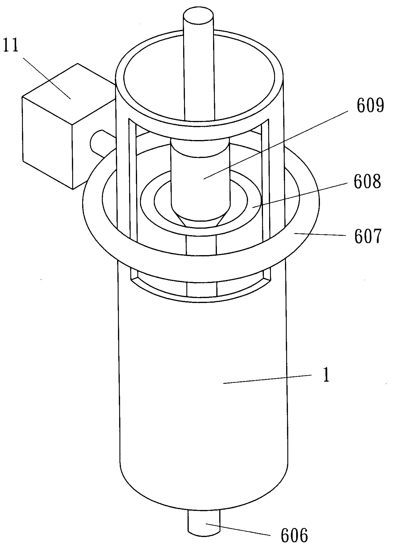
[0057]Refer to FIG. 7B for a VLSED method which stands for vertical large-number synchronizing and line-shape expitaxial deposition. Adopted such a method one set of machine can simultaneously perform deposition to produce ten pieces of coaxial line dual-heterogeneous laser ingots at a length of one meter each; then each laser ingot is cut in sections to form individual coaxial line laser diodes shown in FIG. 8B. At the initial stage of the fabrication process, referring to FIG. 7A and FIG. 7B, ten pieces of subrods 606 at a length of one meter and a diameter of 2 mm are provided and disposed into ten quartz ducts. The subrod 606 is formed through a VGF (Vertical Gradient Freeze) growth method as shown in FIG. 12A that includes the following steps:

[0058]1. dispose an a axial metal conductor rod 1201 engraved with Bragg's grating and embedded with an InP crystal seed 1202, and mount the rod at the bottom of a crucible 1203;

[0059]2. pour...

embodiment 2

The Coaxial Line Laser Diode and the Coaxial Lighting Optical Fiber can be Coupled to Form a Solid State to Provide White-Emitting Luminescence.

[0066]The embodiment 1 set forth above can also be employed to produce respectively three coaxial line laser diodes for red, green and blue colors. Then they can be coupled with three coaxial lighting optical fibers to blend light and form a solid state while-emitting luminescence device. FIG. 11 shows the top view of three color lighting optical fibers coupled in one bundle to blend and generate white-emitting light, with 1101 for the red lighting fiber, 1102 for the green light fiber, 1103 for the blue light fiber, and 1104 for blending of the three colors to provide white-emitting luminescence. Another alternative is providing a blue light coaxial line laser and a yellow light coaxial line laser to respectively inject light in two coaxial lighting optical fibers arranged in a twin-and-twisted manner that complement with each other to form...

embodiment 3

Coaxial Line Laser Diode and Coaxial Lighting Optical Fiber Incorporating with a Fluorescent Set to Form a White-Emitting Luminescence Device

[0067]Form a sub-assembly by coupling a coaxial line laser diode with a coaxial lighting optical fiber to receive light ejection from the laser diode, and install the sub-assembly in a fluorescent tube, a white-emitting luminescence device can be made as shown in FIG. 13, which includes a blue lighting fiber 1301, a second standby lighting fiber 1302 (for the purpose of forming an adjustable structure by providing an extra lighting color), an inner side coated with yellow phosphor 1303 and power supply sockets 1304 to connect the coaxial line laser diode to an external power source. The lighting optical fibers coupled with the coaxial line laser diodes encased in the tube coated with the phosphor to produce white-emitting luminescence is substantially like the conventional tubular fluorescent lamp coated with phosphor to generate white light. H...


PUM


Abstract

The present invention provides a fabrication method of coaxial line laser diodes and a coaxial lighting optical fiber which disperses and guides uniform emission of light from a coaxial line laser diode. The line coaxial laser diode can be extended at a greater length to generate more spontaneous emission photons which are emitted from an elongated tubular active layer. The active layer has a uniform built-in electric field to distribute uniform current therein to get higher quantum efficiency. The length of the coaxial laser diode can be increased through a VLSED method. A longer laser ingot can be produced and cut to a large number of coaxial laser diodes. This method can reduce the waste of cutting in the wafer process and get larger lighting areas. Both the coaxial line laser diode and the coaxial lighting optical fiber can be coupled to form a high efficiency white-emitting luminescence device.

Description

FIELD OF THE INVENTION[0001]The present invention relates to a coaxial line laser diode and particularly to a solid lighting device equipped with high intensity laser diodes and a fabrication method thereof.BACKGROUND OF THE INVENTION[0002]Solid state semiconductor light source has a smaller size, and higher efficiency and greater adaptability, thus has become a very important energy saving product in applications of optical communication, industrial sensors and white-emitting luminescence. The conventional light-emitting diode (LED) generates spontaneous emission through recombination of electrons and holes. The light being generated is a random light with diverse phases, polarities and radiating directions, hence also called incoherent light (referring to FIG. 1A). On the other hand, semiconductor laser light is generated through repetitive optical amplification according to the principle of laser action that has spontaneous emission taking place in a cavity resonator between two ...

Claims


Application Information

Patent Timeline
Patent Type & Authority Applications(United States)
IPC IPC(8): H01S5/125H01S5/12
CPCH01S5/10H01S5/12H01S5/18G02B6/03627G02B6/001G02B6/03611G02B6/0008
Inventor YANG, CHUN-CHU
Owner YANG CHUN CHU
Why Eureka
Try Eureka