Lubricator for textile machine

A textile machine and body technology, which is applied in the field of textile machine lubricating bodies, can solve problems affecting work efficiency and product quality, high fuel consumption, and easy intertwining of twine, etc., and achieve the effects of reasonable design, reduced fuel consumption, and reduced operating procedures

Inactive Publication Date: 2016-07-20
WUJIANG AOMING SPINNING
View PDF6 Cites 2 Cited by
  • Summary
  • Abstract
  • Description
  • Claims
  • Application Information

AI Technical Summary

Problems solved by technology

Using the above-mentioned oil tank to impregnate the twine with oil consumes a lot of oil, and adds a manual operation process, and the twine is easy to entangle with each other, which affects the work efficiency and product quality

Method used


Image

  • Lubricator for textile machine

Examples


Embodiment Construction

[0014] In order to make the technical means, creative features, goals and effects achieved by the present invention easy to understand, the present invention will be further described below in conjunction with specific embodiments.

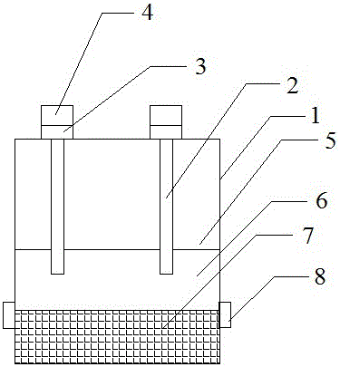
[0015] In order to achieve the above object, the lubricating body for a textile machine is realized by the following technical scheme: the lubricating body for a textile machine includes a main body 1, an oil pipe 2, an oil inlet 3, a dust cover 4, a buffer Suction layer 5, cavity 6, crossbeam 7 and fixed valve 8, oil pipes 2 are respectively installed on the left and right sides of the inner top of the body 1, the top of the oil pipe 2 is provided with an oil inlet 3, and the top of the oil inlet 3 is installed with a dust cover 4. The upper part of the body 1 is provided with a slow suction layer 5, the middle part of the body 1 is provided with a cavity 6, the bottom end of the oil pipe 2 extends into the cavity 6, the bottom of the cavity 6 is ...


PUM


Abstract

The invention discloses a lubricator for a textile machine and relates to the technical field of textile equipment. The lubricator comprises a body (1), oil pipes (2), oil inlets (3), dust covers (4), a buffer suction layer (5), a cavity (6), a transverse beam (7) and fixing valves (8). The oil pipes (2) are mounted on the left and right of the inner top of the body (1) respectively, the top of each oil pipe (2) is provided with one oil inlet (3), the top of each oil inlet (3) is fitted with one dust cover (4), the buffer suction layer (5) is disposed on the upper portion of the body (1), the middle of the body (1) is provided with the cavity (6), the bottom ends of the oil pipes (2) extend into the cavity (6), the transverse beam (7) is mounted at the bottom of the cavity (6), and the cavity (6) and the transverse beam (7) are connected through the fixing valves (8) on two sides of the outer wall. The lubricator for the textile machine is reasonable in design and simple to operate, and effectively reduces oil consumption and shortens tedious operation process.

Description

technical field [0001] The invention relates to the technical field of textile equipment, in particular to a lubricating body for a textile machine. Background technique [0002] Generally, if the hemp thread used in traditional flat knitting machines is not lubricated before weaving, the weaving process will not be smooth due to the roughness of the hemp thread, and the woven cloth will have wrinkles, and countless times of repeated friction between the machine and the hemp thread will make the The yarn is severely dry and worn, destroying the fiber structure on the surface of the hemp thread, producing a large amount of hairiness and flying flowers, resulting in, broken ends, adhesion, pilling, flying flowers and other phenomena. Abrasion produces a large number of flying flowers that pollute the workshop, endangering human health and causing a great waste of resources. [0003] At present, the usual lubricating process is to put the whole bundle of twine into the oil tan...

Claims


Application Information

Patent Timeline
Patent Type & Authority Applications(China)
IPC IPC(8): D04B35/24
CPCD04B35/24
Inventor 严惠明
Owner WUJIANG AOMING SPINNING
Why Eureka
Try Eureka