Processing box

A process box and end plate technology, applied in the field of process boxes, can solve problems such as inconvenient installation, and achieve the effect of easy installation

Active Publication Date: 2016-07-20
NINESTAR CORP +1
View PDF4 Cites 14 Cited by
  • Summary
  • Abstract
  • Description
  • Claims
  • Application Information

AI Technical Summary

Problems solved by technology

In the process of installing the existing process cartridge to the main body of the image forming apparatus, the rotation axis of the photosensitive drum is parallel to the rotation axis of the drive head or the installation direction of the process cartridge is perpendicular to the rotation axis of the photosensitive drum. Installed in the same way, there is a problem that it is not easy to install

Method used


Image

  • Processing box
  • Processing box
  • Processing box

Examples


Embodiment 1

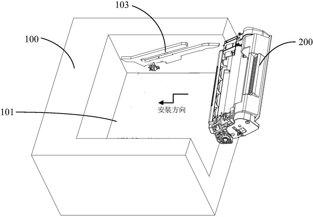
[0062] Such as figure 1 As shown, the main body 100 of the image forming apparatus has a cavity 101 for accommodating the process cartridge. On the two side walls of the cavity 101 are provided guide rails 103 for guiding the installation of the process cartridge, and on one side wall of the cavity 101 are provided A drive head 102 that drives the photosensitive drum of the process cartridge to rotate. The process box 200 is loaded into the main body of the image forming device along the guide rail 103 according to the installation direction set by the main frame of the image forming device (i.e. the predetermined mounting direction of the process box, the following installation directions all represent this meaning), and the process box is installed After being in place, the drive head 102 cooperates with the drive coupler on the process cartridge to drive the photosensitive drum of the process cartridge to rotate.

[0063] For ease of description, the state position where t...

Embodiment 2

[0076] Such as figure 1 As shown, the main body 100 of the image forming apparatus has a cavity 101 for accommodating the process cartridge. On the two side walls of the cavity 101 are provided guide rails 103 for guiding the installation of the process cartridge, and on one side wall of the cavity 101 are provided A drive head 102 that drives the photosensitive drum of the process cartridge to rotate. The process box 200 is loaded into the main body of the image forming device along the guide rail 103 according to the installation direction set by the main frame of the image forming device (i.e. the predetermined mounting direction of the process box, the following installation directions all represent this meaning), and the process box is installed After being in place, the drive head 102 cooperates with the drive coupler on the process cartridge to drive the photosensitive drum of the process cartridge to rotate.

[0077]For ease of description, the state position where th...

Embodiment 3

[0090] Such as Figure 15 , 16 As shown in and 17, the difference between this embodiment and the preceding embodiments is that a rotatable positioning assembly ( Figure 15 , Figure 16 , Figure 17 ), the positioning assembly includes a positioning guide rail 207, a rotating shaft 208 and a deflection elastic member 209, the positioning guide rail 207 is arranged on the housing 201 through the rotating shaft 208, the axis of the rotating shaft 208 is perpendicular to the plane where the positioning guide rail 207 is located, and the positioning guide rail 207 can rotate around the rotating shaft 208 . The deflection elastic member 209 is arranged between the positioning guide rail 207 and the side wall of the housing 201 or the second end plate wall. Under the elastic force of the deflection elastic member 209, the positioning guide rail 207 is not parallel to the plane perpendicular to the rotation axis of the drive head ( Figure 15 ); when the process box is installed...


PUM


Abstract

The invention relates to a processing box, which is detachably arranged in an image forming device host. The processing box comprises a casing and a photosensitive drum, wherein the photosensitive drum is arranged in the casing; one end of the photosensitive drum is provided with a driving shaft coupler used for receiving the driving force of a driving head of the image forming device host; the casing comprises a first end plate and a second end plate which are positioned at the two opposite ends of the casing; an installing guide part protruded out of the end plate is arranged on the first end plate and / or the second end plate; through the installing guide part, the rotating axial line of the photosensitive drum can form an included angle with the rotating axial line of the driving head in the mounting and dismounting process of the processing box. The installing guide part protruded out of the end plate is arranged on the first end plate and / or the second end plate which are arranged at the two opposite ends of the casing of the processing box; the installing guide part can enable the rotating axial line of the photosensitive drum to form the included angle with the rotating axial line of the driving head in the mounting or dismounting process of the processing box; the installation of the processing box is convenient; the engagement of the driving shaft coupler and the driving head of the image forming device host is convenient.

Description

technical field [0001] The present invention relates to a process cartridge used in an image forming apparatus. Background technique [0002] The process cartridge is a cartridge detachably loaded into the main body of the image forming apparatus. As an integral unit, the process cartridge includes a casing, a photosensitive drum, a developing roller and the like arranged in the casing. The process box is detachable from the main body of the image forming apparatus, which is convenient for maintenance of the equipment. The working process of the image forming device adopting the electrophotographic imaging method is as follows: through the light of the image forming device, the photosensitive drum that has been uniformly charged by the charging unit is selectively exposed to form an electrostatic latent image, and the latent image is transferred by the developing roller. The toner is developed into a toner image, and the formed toner image is transferred to a recording medi...

Claims


Application Information

Patent Timeline
Patent Type & Authority Applications(China)
IPC IPC(8): G03G21/18G03G15/00
CPCG03G21/1803G03G21/181G03G21/1842G03G21/186G03G15/757G03G21/1853G03G21/1857G03G21/1864G03G2221/183G03G21/18
Inventor 林传江
Owner NINESTAR CORP
Why Eureka
Try Eureka