
Calibration method of projection module set

A technology of projection module and calibration method, applied in the field of optical imaging, can solve the problem of inability to calibrate the projection module and the like

Inactive Publication Date: 2016-07-20
NINGBO SUNNY OPOTECH CO LTD
View PDF3 Cites 3 Cited by
  • Summary
  • Abstract
  • Description
  • Claims
  • Application Information

AI Technical Summary

Problems solved by technology

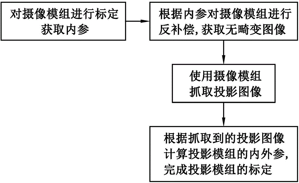
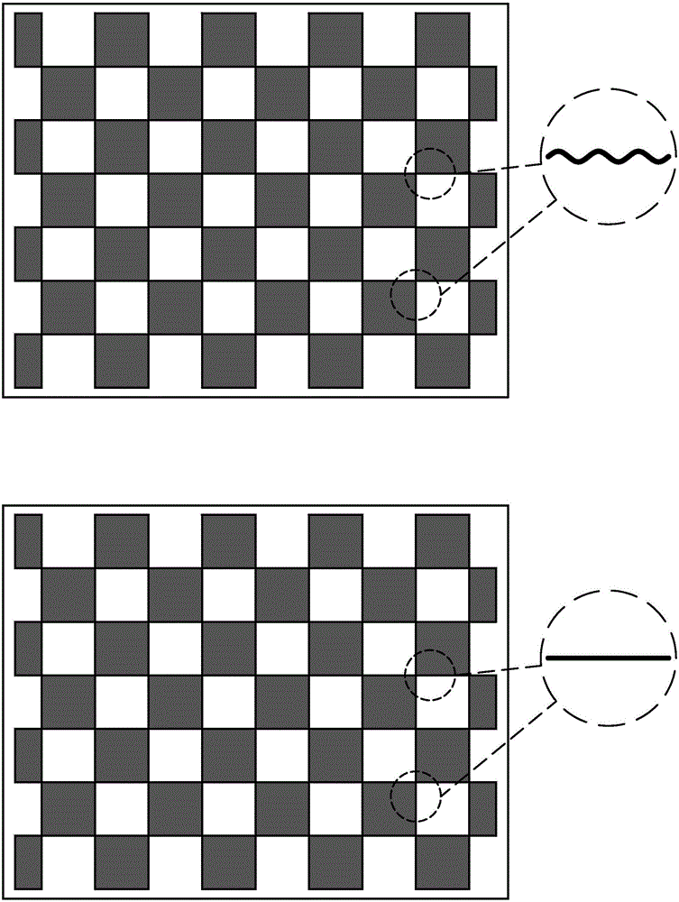
[0008] Another object of the present invention is to provide a calibration method for the projection module, which uses the decompensated camera module to capture the projection image of the projection module, calculates the internal and external parameters of the projection module, and realizes the calibration of the projection module. Solve the traditional problem of not being able to calibrate the projection module

Method used


Image

  • Calibration method of projection module set
  • Calibration method of projection module set

Examples


Embodiment Construction

[0019] The following description serves to disclose the present invention to enable those skilled in the art to carry out the present invention. The preferred embodiments described below are only examples, and those skilled in the art can devise other obvious variations. The basic principles of the present invention defined in the following description can be applied to other embodiments, variations, improvements, equivalents and other technical solutions without departing from the spirit and scope of the present invention.

[0020] A projector is a display device used to display a large screen. The imaging principle of the projector is to convert the illumination beam generated by the light source module into an image beam through the light valve, and then project the image beam to the screen or wall through the lens. surface to form an image.

[0021] One of the basic tasks of computer vision is to calculate the geometric information of objects in three-dimensional space fr...


PUM


Abstract

The invention provides a calibration method of a projection module set. The method includes the following steps that: (1) an image pickup module set is calibrated, and internal parameters are obtained; (2) reverse compensation is performed on the image pickup module set according to the internal parameters, so that a distortion-free image can be obtained; (3) the calibrated image pickup module set is adopted to capture a projection image; and (4) the internal and external parameters of the projection module set are calculated according to the captured projection image, and the calibration of the projection module set is completed. With the calibration method adopted, the decoding rate of the projection image can be greatly improved.

Description

technical field [0001] The invention relates to the field of optical images, in particular to a calibration method for projection modules. Background technique [0002] Whether it is in image measurement or other applications of computer vision, the calibration of imaging parameters is a very critical link and a basic problem in computer vision systems. The accuracy of its calibration directly affects the performance of subsequent vision tasks. [0003] In a specific camera project, although the manufacturer provides most of the parameters of the camera and the corresponding camera lens used, the accuracy of the data provided by the manufacturer often cannot meet the application requirements in the actual project. For example, due to the existence of lens Therefore, in the actual application process, computer vision workers often need to recalibrate the camera according to the actual use situation, obtain specific and accurate internal parameters, and obtain the orientation ...

Claims


Application Information

Patent Timeline
Patent Type & Authority Applications(China)
IPC IPC(8): G06T7/00
Inventor 郑杰张扣文张宝忠
Owner NINGBO SUNNY OPOTECH CO LTD
Learn More