Double-layer bridge structure capable of lowering integral height

A bridge structure and overall height technology, applied in bridges, bridge parts, bridge construction, etc., can solve problems such as unsatisfactory needs, high technical difficulty of long-span bridge structures, increase of overall building height, etc., to achieve a clear and reliable way of bearing force, The construction technology is convenient and mature, and the effect of shortening the length of the bridge

Inactive Publication Date: 2016-07-27
CHINA RAILWAY SIYUAN SURVEY & DESIGN GRP
View PDF6 Cites 2 Cited by
  • Summary
  • Abstract
  • Description
  • Claims
  • Application Information

AI Technical Summary

Problems solved by technology

Especially in the vicinity of railway stations and hubs, the plane and elevation of the line are controlled by multiple conditions such as the existing railway, station location, river, urban roads and buildings. In the past, portal piers, frame bridges, large Span bridges and other structures can no longer meet the needs of many new railway small-angle interchange projects
For example, the technical difficulty of the long-span bridge structure is high, and the additional investment is huge; the frame bridge does not meet the crossing requirements of the road and river under the bridge; figure 1 As shown, the beam of the portal pier and the height of the upper beam structure increase the overall building height and increase the scale of bridge construction. Even under the condition of limited elevation, the clearance requirements of the lower railway cannot be met, which directly leads to the failure of the line plan

Method used


Image

  • Double-layer bridge structure capable of lowering integral height
  • Double-layer bridge structure capable of lowering integral height
  • Double-layer bridge structure capable of lowering integral height

Examples


Embodiment Construction

[0018] In order to better understand the technical solution of the present invention, the present invention will be further described in detail below in conjunction with the accompanying drawings and specific embodiments.

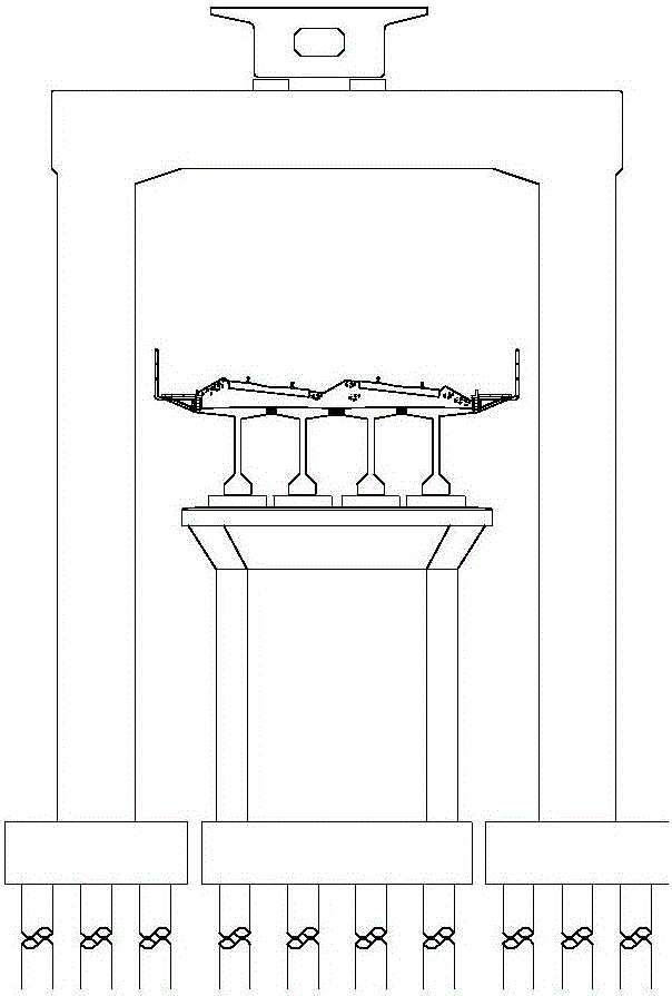
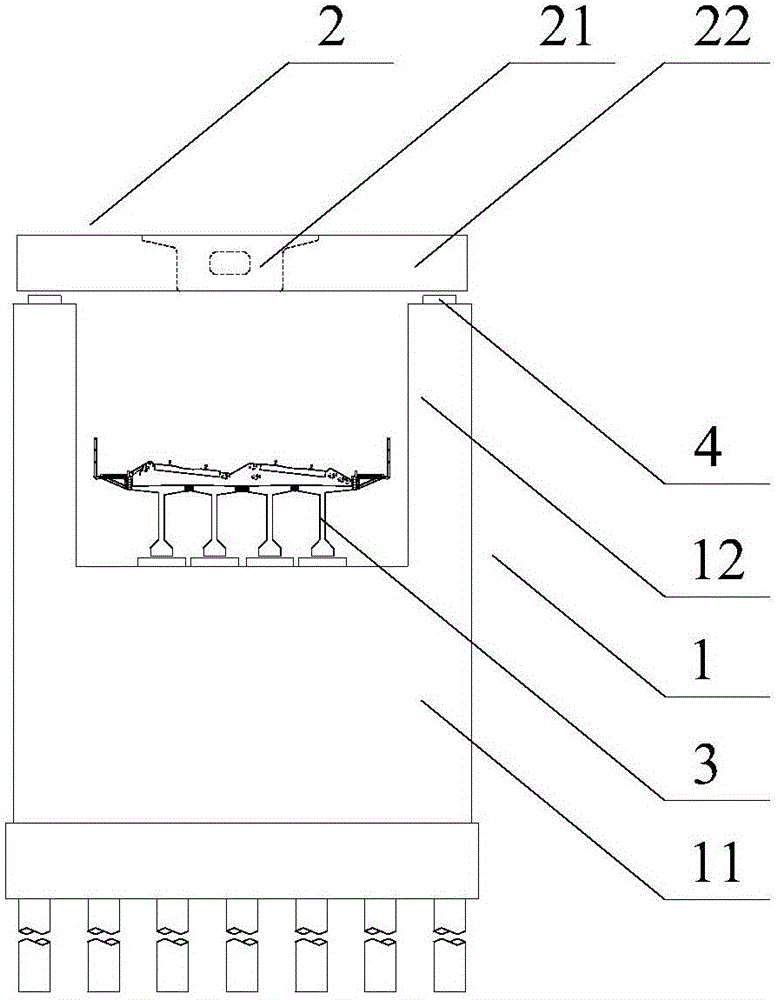
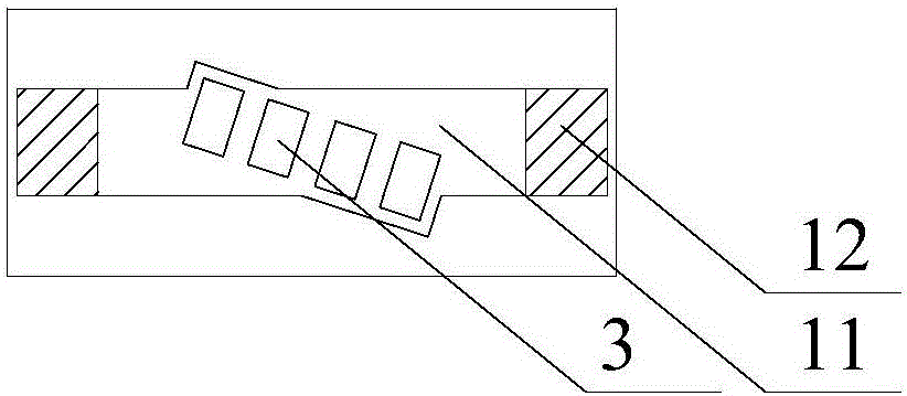
[0019] Such as figure 2 As shown, a double-layer bridge structure with reduced overall height includes a common pier column 1, an upper railway beam part 2 and a lower railway beam part 3, and the common pier column 1 is composed of a lower solid pier 11 and an upper double-column pier 12 One-piece structure, the upper double-column pier 12 is located above the two sides of the lower solid pier 11, such as image 3 and Figure 4 As shown, the lower railway beam part 3 is horizontally arranged on the upper surface of the lower solid pier 11, and the central axis of the lower railway beam part 3 intersects the central axis of the lower solid pier 11 non-perpendicularly, and the upper end surfaces of the upper double-column pier 12 are provided with supports...


PUM


Abstract

The invention discloses a double-layer bridge structure capable of lowering the integral height. The double-layer bridge structure comprises a public pier column, an upper layer railway beam part and a lower layer railway beam part, wherein the public pier column consists of a lower entity pier and an upper double-column pier; an upper layer railway longitudinal beam of the upper layer railway beam is erected on the upper double-column pier of the public pier column through outwards ararnging support bodies at two sides of the same horizontal surface; the support bodies are of transversely widened prestressed concrete structures with tensioned transverse prestressed bars. The double-layer bridge structure provided by the invention has the advantages that the control factor of clear height limitation can be avoided; the plane control condition can also be met; meanwhile, the stress requirements of the structure under the upper and lower layer railway load effect can be met; the construction technology is convenient and mature; the building height of the structure is obviously reduced; the bridge length is reduced; the building scale is reduced; the obvious economic benefits are realized; the railway small-angle grade separation engineering requirements under the limitation conditions of various factors such as plane and vertical surface spaces can be met.

Description

technical field [0001] The invention relates to a double-layer bridge in traffic engineering, in particular to a double-layer bridge structure with reduced overall height. Background technique [0002] With the rapid development of my country's railway construction, the road network is becoming more and more dense, and the small-angle railway interchange is inevitable. Especially in the vicinity of railway stations and hubs, the plane and elevation of the line are controlled by multiple conditions such as the existing railway, station location, river, urban roads and buildings. In the past, portal piers, frame bridges, large Structures such as span bridges have been unable to meet the needs of many new railway small-angle interchange projects. For example, the technical difficulty of the long-span bridge structure is high, and the additional investment is huge; the frame bridge does not meet the crossing requirements of the road and river under the bridge; figure 1 As show...

Claims


Application Information

Patent Timeline
Patent Type & Authority Applications(China)
IPC IPC(8): E01D12/00E01D19/00E01D19/02
CPCE01D12/00E01D19/00E01D19/005
Inventor 文望青许三平薛照钧康红兵杜伟柳鸣董伟余晓燕周继
Owner CHINA RAILWAY SIYUAN SURVEY & DESIGN GRP
Why Eureka
Try Eureka