
Variable Stiffness Broadband Resonant Mechanism

A technology of broadband resonance and variable stiffness, which is applied in the field of variable stiffness broadband resonance mechanisms, can solve the problems of narrow resonance frequency range and excessive power at the crossover frequency of fixed stiffness resonance mechanisms, so as to reduce stress and strain, reduce input power, The effect of expanding the amplitude range

Inactive Publication Date: 2018-07-13
JILIN UNIV
View PDF6 Cites 0 Cited by
  • Summary
  • Abstract
  • Description
  • Claims
  • Application Information

AI Technical Summary

Problems solved by technology

[0005] The technical problem to be solved by the present invention is to overcome the problems existing in the prior art that the power of the vibrating table is too large at the crossover frequency in the frequency sweep experiment, and the resonant frequency range of the fixed stiffness resonant mechanism is narrow, and provides a variable Rigid Broadband Resonant Mechanism

Method used


Image

  • Variable Stiffness Broadband Resonant Mechanism
  • Variable Stiffness Broadband Resonant Mechanism
  • Variable Stiffness Broadband Resonant Mechanism

Examples


example

[0089] In this example, the leaf spring 1502 is selected as 200mm in length and 50mm in width. In order to adjust the stiffness, three thicknesses are set to 2.6mm, 3.5mm, and 4.06mm, corresponding to the initial stiffness of 10N / mm, 20N / mm, and 30N / mm. , the angle between No. 1 rod 2105 and No. 2 rod 2104 is 110°, the initial installation angle θ1 is 60°, and θ2 is 10°. The length of No. 1 rod 2105 is 60mm, and the length of No. 2 rod 2104 is 45mm.

[0090] Different initial stiffnesses of leaf spring groups 15 are set respectively, and the output force varies with displacement as shown in Figure 18 As shown, the output stiffness is as Figure 19 as shown,

[0091] Figure 18 It shows the relationship between the force and displacement of the output end when the superimposed stiffness of different leaf springs is different

[0092] Figure 19 The variation trend of the stiffness with the displacement of the variable stiffness mechanism is shown when different leaf spring...


PUM


Abstract

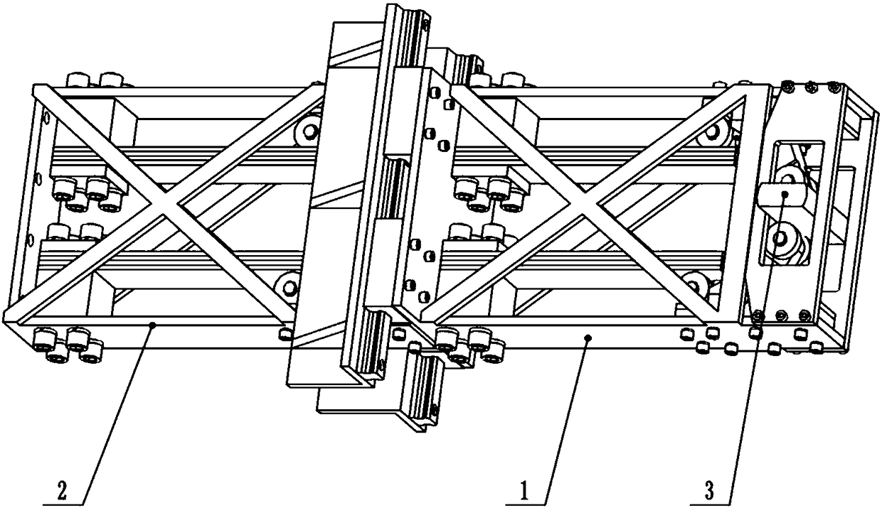
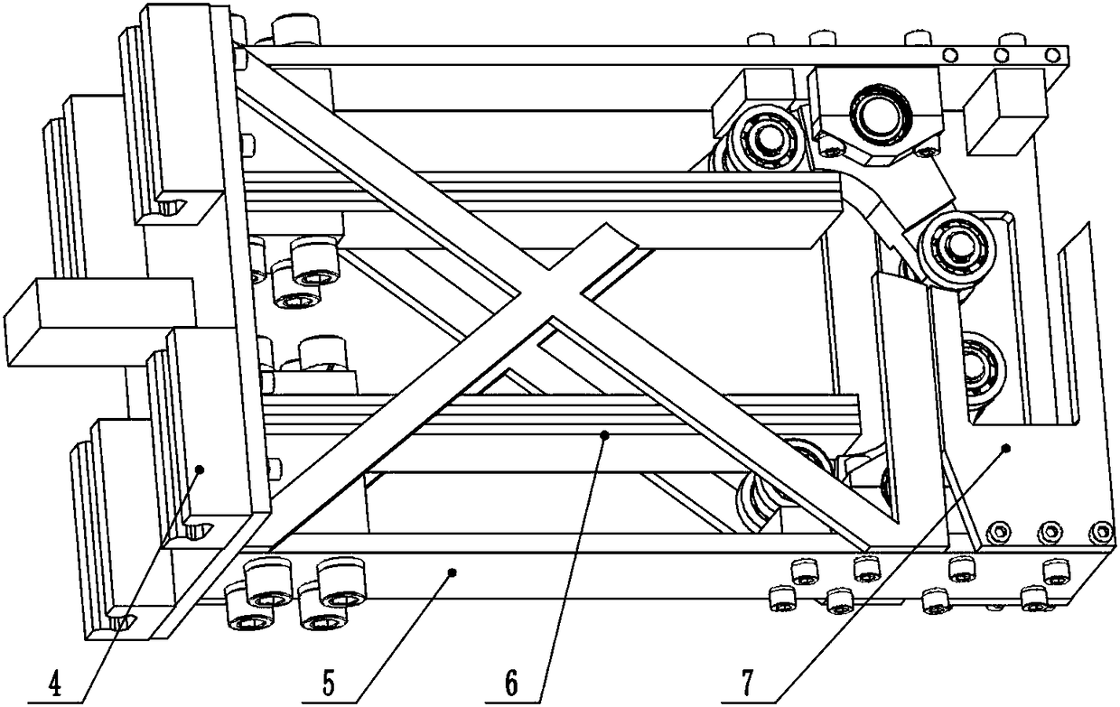
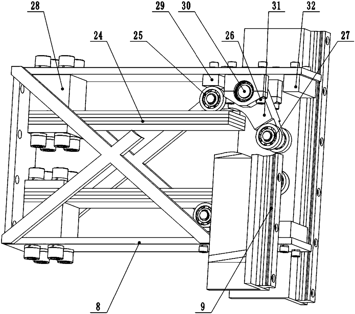
The invention discloses a variable-rigidity broadband resonance mechanism and aims to solve the problem that a vibration table is too high in power at cross-over frequency in a frequency sweeping experiment and the problem that a resonance frequency interval is narrow when a fixed-rigidity resonance mechanism is used.The variable-rigidity broadband resonance mechanism comprises a resonance mechanism front arm, a resonance mechanism rear arm and an output rod, the resonance mechanism rear arm is positioned on the left side of the resonance mechanism front arm, four sliders at the left end of the resonance mechanism front arm are in sliding fit with two guide rails at the right end of the resonance mechanism rear arm, a rear end tongue of the resonance mechanism front arm is positioned between two rear variable-rigidity mechanisms in the resonance mechanism rear arm, upper and lower end faces of the rear end tongue contact with number 2 rear bearings in rear lever mechanisms of the two rear variable-rigidity mechanisms, the output rod is mounted in rectangular through holes of two guide rods in the resonance mechanism front arm, left and right arc faces of the output rod are in contact connection with left and right inner side faces of the rectangular through holes of the guide rods of the resonance mechanism front arm, and upper and lower surfaces of the output rod contact with number two front bearings in front lever mechanisms of two front variable-rigidity mechanisms in the resonance mechanism front arm.

Description

technical field [0001] The invention relates to a resonance device for a vibrating table, more precisely, the invention relates to a variable stiffness wide-frequency resonance mechanism. Background technique [0002] The vibration table is a device that can reproduce the vibration environment of the test piece, and is used to study the reliability and stability of the test piece under different vibration environments. [0003] When using a vibrating table to perform a frequency sweep test on the specimen, since the exciting force curve needs to be smooth, that is, there is a smooth crossover point. The frequency corresponding to this point is the crossover frequency. By calculating the input power corresponding to each frequency, it can be known that The power corresponding to the crossover frequency is the maximum value, that is, if a certain frequency is too high, the total power of the system will increase, which directly increases the manufacturing cost and the use cost...

Claims


Application Information

Patent Timeline
Patent Type & Authority Patents(China)
IPC IPC(8): G01M7/02
CPCG01M7/022
Inventor 孙晓王勇威周兴华唐可洪王一名
Owner JILIN UNIV
Learn More