PLL automatic test circuit and test method

An automatic test and circuit technology, applied in the direction of measuring electricity, measuring electrical variables, electronic circuit testing, etc., can solve the problems that cannot be completed automatically, the test results need manual observation, and cannot cover the working range of PLL, so as to save risks and workload , Avoid the effect of incomplete test coverage

Active Publication Date: 2016-07-27
FUZHOU ROCKCHIP SEMICON
View PDF6 Cites 6 Cited by
  • Summary
  • Abstract
  • Description
  • Claims
  • Application Information

AI Technical Summary

Problems solved by technology

The disadvantages of this method are also obvious. The time to find the problem is too late. At this time, the chip has been packaged. If the chip is found to be scrapped, the packaging cost will be wasted; It is impossible to ensure that the PLL can work normally in all operating ranges; the test results need manual observation and cannot be completed automatically

Method used


Image

  • PLL automatic test circuit and test method

Examples


Embodiment Construction

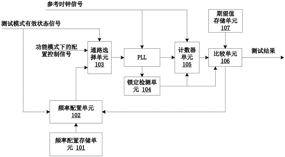
[0024] Such as figure 1 As shown, the PLL automatic test circuit of the present invention includes a frequency configuration storage unit 101, a frequency configuration unit 102, a path selection unit 103, a lock detection unit 104, a counter unit 105, a comparison unit 106 and an expected value storage unit 107; Unit 101, frequency configuration unit 102, path selection unit 103 are connected to the PLL in turn; and the frequency configuration unit 102 and path selection unit 103 are all connected to the test mode valid status bit signal; the path selection unit 103 is also connected to the Configure the control signal; the lock detection unit 104, PLL, counter unit 105, comparison unit 106 and expected value storage unit 107 are connected in sequence; the lock detection unit 104 is also connected to the counter unit 105, the comparison unit 106; the PLL, counter The unit 105 is also connected to the reference clock signal; the comparison unit 106 is also connected to the fre...


PUM


Abstract

The invention provides a PLL automatic test circuit, and the circuit comprises a frequency allocation memory unit, a frequency allocation unit, a pathway selection unit, a lock detection unit, a counter unit, a comparison unit and a desired value memory unit; the frequency allocation memory unit, the frequency allocation unit and the pathway selection unit are connected with the PLL in sequence, and the frequency allocation unit and the pathway selection unit are connected with a test mode effective state bit signal; the pathway selection unit is connected with an allocation control signal under a function mode; the lock detection unit, the PLL, the counter unit, the comparison unit and the desired value memory unit are connected in sequence; the lock detection unit is also connected with the counter unit and the comparison unit; and the PLL and the counter unit are connected with a reference clock signal. According to the invention, the circuit and method can perform a full spectrum band covering test on the PLL in chip CP test phase, can judge if the function of the PLL is correct through automatic calculation and can directly get the result.

Description

technical field [0001] The invention relates to a PLL automatic test circuit and a test method. Background technique [0002] With the gradual expansion of the scale of the SOC chip, the clock demand of the SOC chip is also getting higher and higher, and the source of the clock in the chip is the PLL (Phase Locked Loop) circuit, so the quality of the PLL circuit directly affects the normal operation of the SoC chip. If the PLL cannot work, the entire SOC chip can only be scrapped, and then the entire hardware system using the SOC chip will collapse. At the same time, because the high-performance PLL circuit is usually an analog circuit, the current test method is to let the chip start to work directly after the chip is packaged, and then observe through the chip PLL signal observation pin to see whether the PLL frequency and oscillation characteristics meet expectations. , so as to judge whether the PLL of the chip can work normally. The disadvantage of this method is also...

Claims


Application Information

Patent Timeline
Patent Type & Authority Applications(China)
IPC IPC(8): G01R31/28
CPCG01R31/2882
Inventor 廖裕民叶院红
Owner FUZHOU ROCKCHIP SEMICON
Why Eureka
Try Eureka