
Selfie stick based on fractal structure

A fractal structure, selfie stick technology, applied in the direction of telephone structure and other directions, can solve the problems of easy to produce jitter, unable to fix the selfie stick, unable to form a stable structure with fractal body, etc., and achieve the effect of simple structure transformation and stable shooting.

Inactive Publication Date: 2016-07-27
SUZHOU HEXINMEI ELECTRONICS SCI & TECH CO LTD
View PDF6 Cites 0 Cited by
  • Summary
  • Abstract
  • Description
  • Claims
  • Application Information

AI Technical Summary

Problems solved by technology

[0008] The technical problem to be solved by the present invention is to overcome the deficiencies of the prior art and provide a selfie stick based on a fractal structure, which solves the problem that the existing selfie stick can only be taken by holding the stick body, which is prone to shaking and cannot be used by the selfie stick. Fixed, the problem that the rod body cannot be fractalized to form a stable structure to assist photography

Method used


Image

  • Selfie stick based on fractal structure
  • Selfie stick based on fractal structure

Examples


Embodiment 1

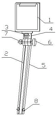
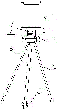
[0026] The selfie stick used in this implementation includes a fixed mount 1, a hand-held pole 2 and a control circuit 3 arranged on the hand-held pole. The hand-held pole 2 is made up of a fixed pole 4 and a splitting pole. The fixed frame 1 is fixedly connected, and the other end of the fixed rod 4 is provided with a through hole; the split rod is composed of three rod bodies 5 equal in length, and one end of each rod body 5 is provided with an opening; the selfie rod also includes a bolt 6 And the nut 7, the bolt 6 stretches out after passing through the through hole of the fixed rod 4 and the openings of the three rod bodies 5, and is reinforced or loosened by the nut 7; the three rod bodies 5 are fractal when the nut 7 is loosened Form a tripod structure. Further, threads are provided on the through holes of the fixing rod 4 and the inner walls of the openings of the three rod bodies 5 . By increasing the thread, the bolt 6 can also play a fixing role when passing throug...

Embodiment 2

[0028] The selfie stick of the present embodiment comprises a fixed frame 1, a hand-held pole 2 and a control circuit 3 arranged on the hand-held pole. The said hand-held pole 2 is composed of a fixed pole 4 and a split pole. The frame 1 is fixedly connected, and the other end of the fixed rod 4 is provided with a through hole; the split rod is composed of three rod bodies 5 equal in length, and one end of each rod body 5 is provided with an opening; the selfie rod also includes bolts 6 and Nut 7, the bolt 6 protrudes after passing through the through hole of the fixed rod 4 and the openings of the three rod bodies 5, and is reinforced or loosened by the nut 7; the three rod bodies 5 are fractally formed when the nut 7 is loosened Tripod structure. And the three rod bodies 5 are all telescopic rods, that is, a telescopic structure can be used to extend the length of the selfie stick, which can realize extension and contraction and save space. Preferably, the bottoms of the th...


PUM


Abstract

The invention discloses a selfie stick based on fractal structure. The selfie stick comprises a fixing frame (1), a handheld rod (2) and a control circuit (3) arranged on the handheld rod (2). The handheld rod (2) is composed of a fixing rod (4) and split rods. One end of the fixing rod (4) is fixedly connected with the fixing frame (1). The other end of the fixing rod (4) is equipped with a via hole. The split rods are composed of three rod bodies (5) with equal lengths. One end of each rod body (5) is equipped with an open pore. The selfie stick also comprises a bolt (6) and a screw (7). The bolt (6) penetrates the via hole of the fixing rod (4) and the open pores of the three rod bodies (5), then stretches out and is fastened or loosen by the screw (7). The three rod bodies (5) form a tripod structure by fractal when looseness is carried out by the screw (7). According to the selfie stick, a user does not need to hold the whole rod by using the stability of the tripod structure, photographing is carried more stably, and the selfie stick has an anti-shake function.

Description

technical field [0001] The invention relates to a selfie stick based on a fractal structure, which belongs to the technical field of photographic auxiliary tools. Background technique [0002] At present, with the improvement of people's living standards and the rapid development of electronic products, the pixels of mobile phone cameras are getting higher and higher, and mobile phone photography is being widely used in more and more life scenes. Mobile phones have become a way for people to record life Handy tool. In order to make it more convenient for users to take pictures with their mobile phones, people have researched and invented the selfie stick. [0003] For the selfie stick, it often includes a fixed frame, a hand-held stick and a control circuit arranged on the hand-held stick. The fixing frame is used to fix the mobile phone, the hand-held rod is used to provide hand-holding, and the control circuit is used to provide users with wireless connection and remote ...

Claims


Application Information

Patent Timeline
Patent Type & Authority Applications(China)
IPC IPC(8): H04M1/12
CPCH04M1/12
Inventor 胡国良
Owner SUZHOU HEXINMEI ELECTRONICS SCI & TECH CO LTD
Learn More