
Electronic component seat of annular structure

A technology of electronic components and ring structure, which is applied in the direction of electrical components, printed circuits assembled with electrical components, and printed circuits connected with non-printed electrical components. It can solve the problem of the small number of pins 23 and increase the number of pins. , view convenient effect

Inactive Publication Date: 2016-07-27
GUANGZHOU CHENGHAN ELECTRONICS TECH CO LTD
View PDF9 Cites 0 Cited by
  • Summary
  • Abstract
  • Description
  • Claims
  • Application Information

AI Technical Summary

Problems solved by technology

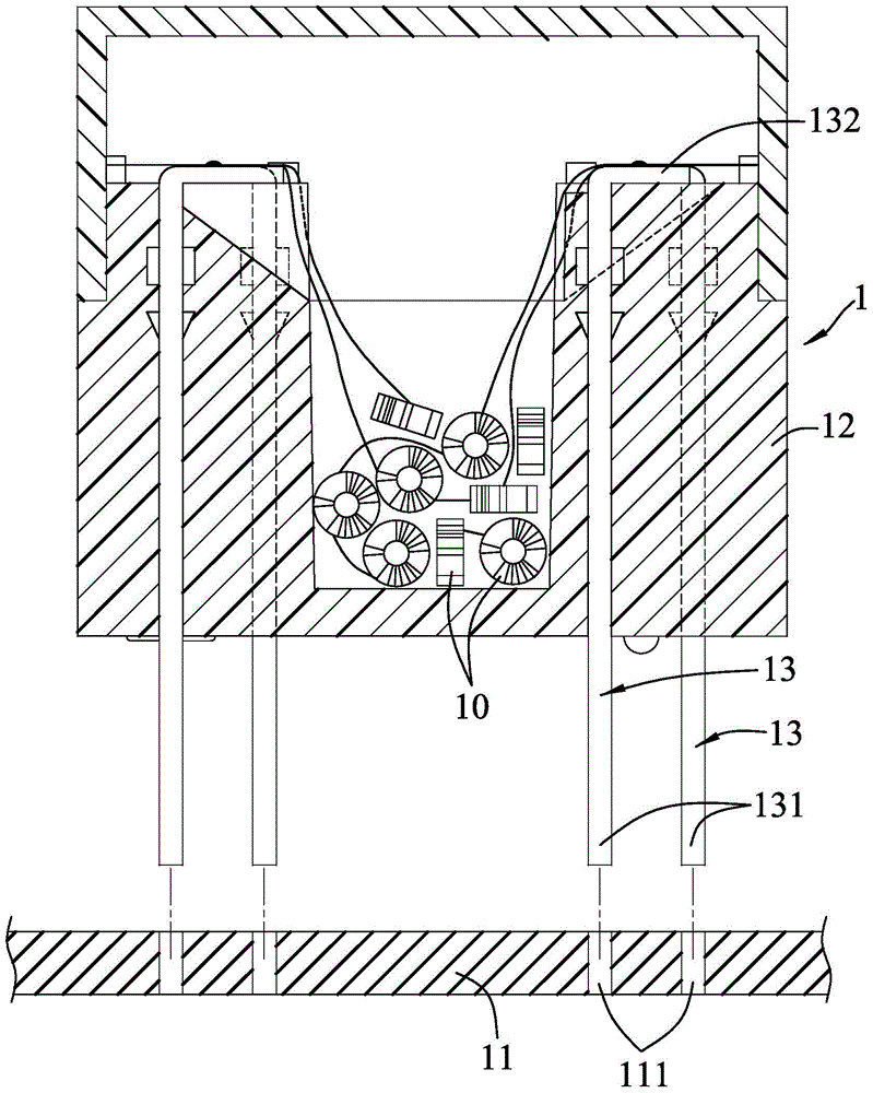
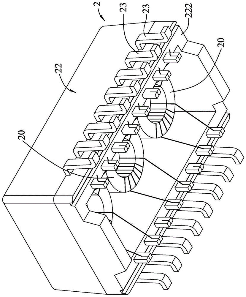
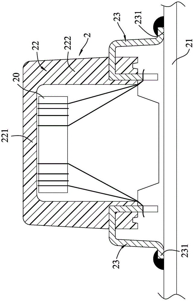
[0006] When the existing electronic component holder 2 is assembled, although it is not necessary to provide jacks on the circuit board 21, and the overall volume can be reduced, each pin 23 must have the protruding foot section 231 extending horizontally, which is subject to The structure of the seat body 22 is limited, the pins 23 can only be arranged on the surrounding wall 222, and the protruding foot section 231 is horizontally protruded from the outer periphery of the seat body 22, because the volume is constant , the total length of the surrounding wall 222 is fixed, so although the volume of the electronic component seat 2 known as SMD can be reduced, the number of the pins 23 that can be installed is relatively small

Method used


Image

  • Electronic component seat of annular structure
  • Electronic component seat of annular structure
  • Electronic component seat of annular structure

Examples


Embodiment Construction

[0025] The present invention will be described in detail below in conjunction with the accompanying drawings and embodiments.

[0026] refer to Figure 4 , 5 , 6, a first embodiment of the electronic component seat of the present invention can be installed with several coils 30, and is electrically connected with a circuit board 31, the electronic component seat includes a seat body 4, several coils installed on the seat body 4 The outer pins 5 on the upper body, and several inner pins 6 installed on the base body 4 . The seat body 4 includes a hollow rectangular outer surrounding wall 41, an inner surrounding wall 42 with an area smaller than the outer surrounding wall 41 and a hollow rectangular structure, a perforation 43 surrounded by the inner surrounding wall 42, a connecting An annular base wall 44 adjacent to the circuit board 31 between the outer surrounding wall 41 and the inner surrounding wall 42 , and a ring-shaped base wall 44 jointly defined by the outer surro...


PUM


Abstract

The invention discloses an electronic component seat of an annular structure. The electronic component seat can be installed on a circuit board through electrical connection and comprises a seat body, and a plurality of external connection pins and a plurality of internal connection pins which are installed on the seat body. The seat body comprises at least one inner surrounding wall for installing the internal connection pins thereon, one outer surrounding wall which is used for installing the external connection pins thereon and surrounds the periphery of the inner surrounding wall, one annular basal wall connected between the outer surrounding wall and the inner surrounding wall, and one annular space commonly defined by the outer surrounding wall, the inner surrounding wall and the annular basal wall. According to the invention, through additional arrangement of the inner surrounding wall for installing the internal connection pins thereon on the seat body, under the condition that the volume is not changed, the quantity of the connection pins of the electronic component seat can be increased.

Description

technical field [0001] The invention relates to an electronic component seat, in particular to a ring-shaped electronic component seat suitable for being mounted on a circuit board in a surface bonding manner. Background technique [0002] An electronic component holder is an electronic product that can accommodate electronic parts such as coils, etc. The electronic product is electrically connected to a circuit board. With the different ways of assembling on the circuit board, the existing electronic component holder It can be divided into two types: plug-in type and surface-mounted type. Among them, the plug-in electronic component seat can also be called a dual in-line package (dualin-linepackage, referred to as DIP), which uses the pins that go down through the circuit board, and the through-hole technology (through-hole technology) Mates bonded to the circuit board. The surface-mounted electronic component holders can also be called surface-mount devices (SMD for shor...

Claims


Application Information

Patent Timeline
Patent Type & Authority Applications(China)
IPC IPC(8): H05K1/18H05K3/34
CPCH05K1/184H05K3/3447
Inventor 潘詠民范仲成
Owner GUANGZHOU CHENGHAN ELECTRONICS TECH CO LTD
Learn More