
Encapsulation shell structure with double rows of pins extending from side surfaces

A technology of encapsulating shells and double-row tubes, which is applied in the direction of electrical components, electric solid devices, circuits, etc., can solve the problems of poor heat dissipation and inability to meet the needs of SIP systems, and achieve the effect of increasing the number of pins

Inactive Publication Date: 2015-06-03
XIAN TONGRUI NEW MATERIAL DEV
View PDF0 Cites 0 Cited by
  • Summary
  • Abstract
  • Description
  • Claims
  • Application Information

AI Technical Summary

Problems solved by technology

For power modules with power devices at the bottom, the cooling effect is even worse
The applicant provided a structure for leading out the pins on the side, but the way of leading out in a single row still cannot meet the needs of the SIP system

Method used


Image

  • Encapsulation shell structure with double rows of pins extending from side surfaces

Examples


Embodiment Construction

[0009] The implementation of the present invention will be described in detail below in conjunction with the drawings and examples.

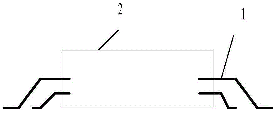
[0010] like figure 1 As shown, a package shell structure with double rows of pins drawn from the side includes a flat shell 2, two rows of pins 1 are drawn from the side of the flat shell 2, and the pins 1 are drawn downwards, and the end is flat with the bottom of the flat shell 2. together. The two rows of pins 1 have a pitch of 2.54 mm between the pins in each row, totaling 20 pins; the pitch between the two rows is also 2.54 mm, and the horizontal difference between the second row and the first row is 1.27 mm. Ensure that each pin can be connected to the substrate using gold wires during internal assembly.

[0011] Compared with the original scheme, the present invention doubles the number of pins without increasing the area, and is suitable for complex integrated systems such as SIP.


PUM


Abstract

The invention discloses an encapsulation shell structure with double rows of pins extending from side surfaces. The encapsulation shell structure comprises a flat shell, wherein the double rows of pins extend from the side surfaces of the flat shell, the pins downward extend out, and the end parts of the pins are flush with the bottom of the flat shell. The side surfaces of the encapsulation shell structure are provided with two rows of pins, so that the pin quantity of the module are effectively improved, and the outer pin demands of complicated systems such as an SIP (System In Package) can be met.

Description

technical field [0001] The invention belongs to the technical field of packaging, and in particular relates to a packaging shell structure with double rows of pins drawn out from the side. Background technique [0002] The power module is easy to generate heat, and its heat dissipation problem has always been a research object in the industry, among which, the heat dissipation capability of its packaging shell is very important. The pins of the current packaging shell are drawn out from the bottom surface and inserted on the device, and the pins are drawn out from the bottom, which reduces the heat dissipation area of ​​the bottom. For power modules with power devices at the bottom, the heat dissipation effect is even worse. The applicant provides a structure for leading out pins from the side, but the way of leading out in a single row still cannot meet the needs of the SIP system. Contents of the invention [0003] In order to overcome the above-mentioned shortcomings ...

Claims


Application Information

Patent Timeline
Patent Type & Authority Applications(China)
IPC IPC(8): H01L23/31H01L23/48
Inventor 刘宝华
Owner XIAN TONGRUI NEW MATERIAL DEV
Learn More