Vacuum self-priming pump with suction aid mechanism

A self-priming pump and vacuum pump technology, applied in the direction of the pump, the components of the pumping device for elastic fluid, the driving pump, etc., can solve the problems of burning out the motor or diesel engine, idling of the pump, unable to transport the liquid medium at the pump inlet, etc. , to achieve the effect of improving the suction stroke and protecting the safety of operation

Active Publication Date: 2018-04-10
浙江永球科技有限公司
View PDF6 Cites 0 Cited by
  • Summary
  • Abstract
  • Description
  • Claims
  • Application Information

AI Technical Summary

Problems solved by technology

Its main disadvantage is that when the pump is started, the pump cavity must be filled with liquid medium or vacuum. When the pump is started and the pump cavity is filled with air, the pump will run idly, unable to transport the liquid medium from the pump inlet to the outlet, and even burn out the impeller idling Electric motor or diesel engine; the maximum suction of existing products is less than 7 meters, and the suction is low

Method used


Image

  • Vacuum self-priming pump with suction aid mechanism
  • Vacuum self-priming pump with suction aid mechanism
  • Vacuum self-priming pump with suction aid mechanism

Examples


Embodiment Construction

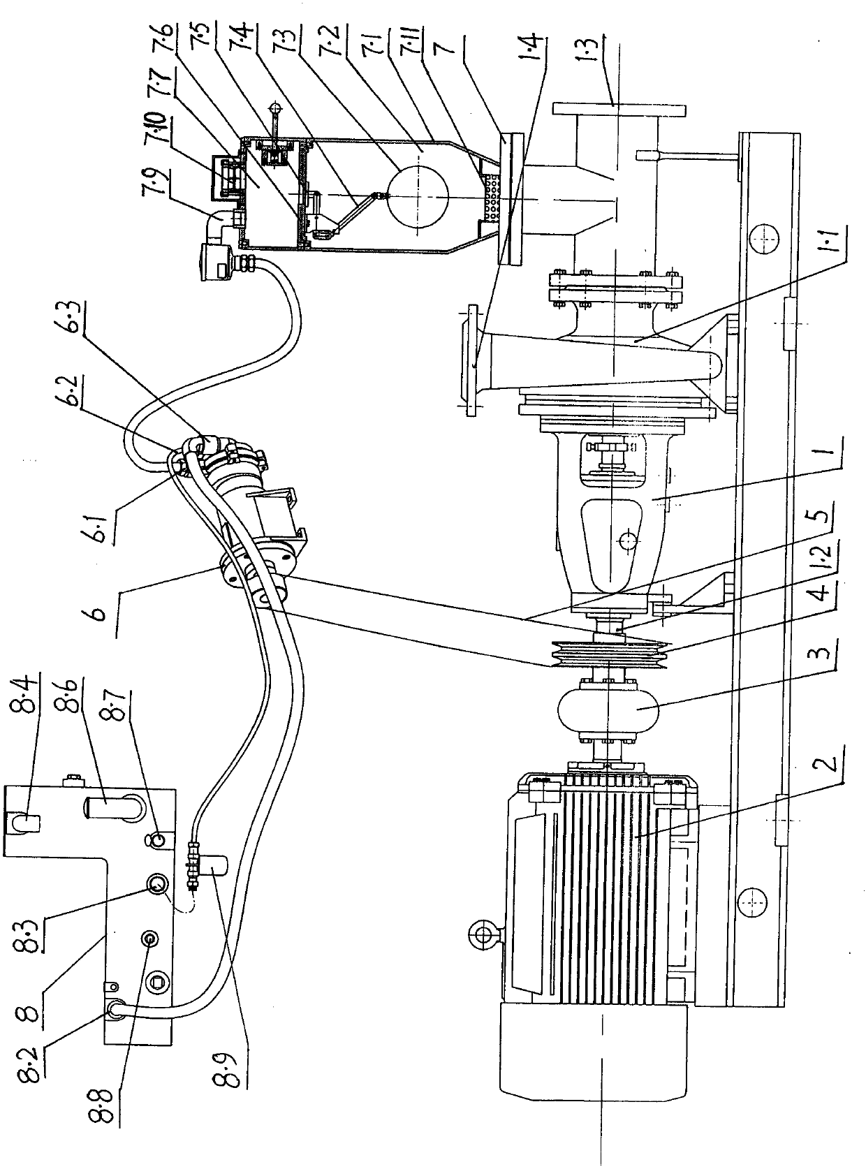
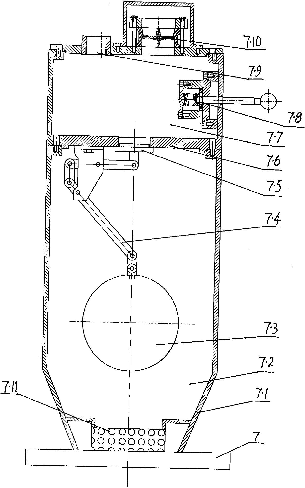
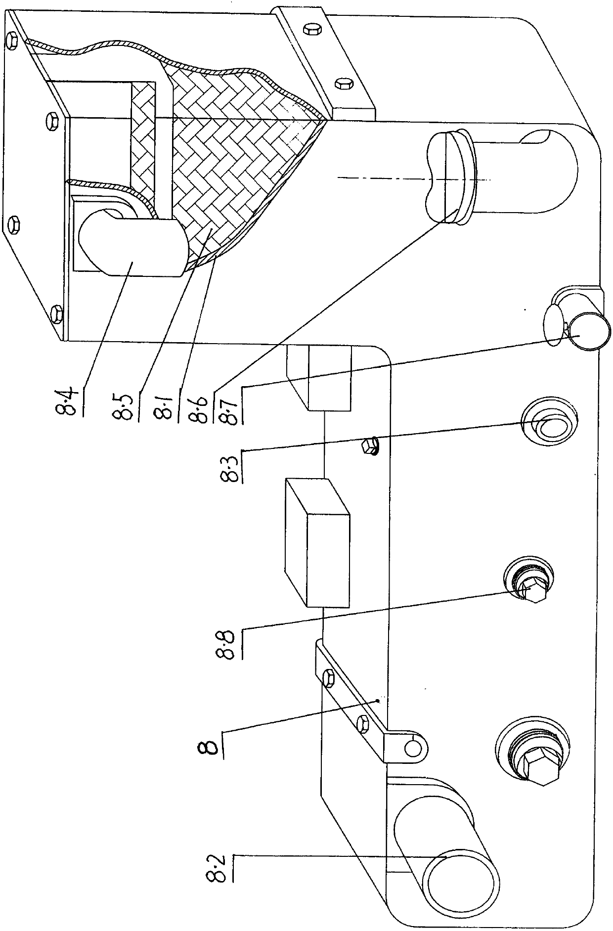
[0013] Such as figure 1 The vacuum self-priming pump with suction-assisted mechanism shown includes a pump 1 and a power part. The pump 1 includes a pump body 1.1, a pump shaft 1.2, and an impeller. The pump body 1.1 has an inlet passage 1.3 and an outlet passage 1.4. The impeller is fixedly connected, and the other end of the pump shaft 1.2 is connected to the output shaft of the power part through the coupling 3. The power part adopts the motor 2 or diesel engine; a suction-assisting mechanism is provided on the inlet passage 1.3 of the pump body 1.1. Water guide 7, vacuum pump 6, and condenser 8. The rotating shaft of vacuum pump 6 is connected by belt 5 and pulley 4 fixed on pump shaft 1.2. When pump shaft 1.2 rotates, vacuum pump 6 is driven to rotate simultaneously, and first inlet 6.1 of vacuum pump 6 passes The vacuum water guide 7 communicates with the inlet channel 1.3 of the pump body 1.1, the vacuum pump outlet 6.3 communicates with the condenser inlet 8.2, and the c...


PUM


Abstract

The invention relates to a vacuum self-sucking pump with a suction aid mechanism. The vacuum self-sucking pump comprises a pump body and a power part, wherein mainly the suction aid mechanism is disposed at an inlet channel of the pump body, and the suction aid mechanism is composed of a vacuum water diversion device, a vacuum pump and a condenser; a spindle of the vacuum pump is connected to a belt wheel fixed on a pump shaft by a belt, a first inlet of the vacuum pump communicates with the inlet channel of the pump body by the vacuum water diversion device, an outlet of the vacuum pump communicates with an inlet of the condenser, an outlet of the condenser communicates with a second inlet of the vacuum pump; an inlet of a water diversion chamber of the vacuum water diversion device communicates with the inlet channel of the pump body, and the first inlet of the vacuum pump communicates with a vacuum air vent disposed inside the vacuum chamber of the vacuum water diversion device; and oil is injected in a machine body of the condenser, an inlet of the condenser is located above the oil plane, an outlet of the condenser is located under the oil plane, and an air vent is disposed in the upper plane of the machine body of the condenser. When the pump is switched on, the suction aid mechanism starts work at the same time and suck air in the pump chamber. In this way, normal operation of the pump can be implemented and the pump operation can be kept safe; and a suction distance and efficiency can be increased.

Description

Technical field [0001] The invention belongs to the field of pumps, and particularly relates to a vacuum self-priming pump. Background technique [0002] The vacuum self-priming pump is composed of a pump part and a power part. The pump part includes a pump body, a pump shaft, and an impeller. The pump body has an inlet passage and an outlet passage. One end of the pump shaft is fixedly connected to the impeller, and the other end of the pump shaft is connected to the output shaft of the power part through a coupling. The power part adopts electric motor or diesel engine. The output shaft of the motor or diesel engine drives the pump shaft and impeller to rotate, sucking the liquid from the pump inlet to the pump outlet, and realizing the delivery of the liquid medium. The main disadvantage is that the pump cavity must be filled with liquid medium or vacuum when the pump is started. When the pump cavity is filled with air when the pump is started, the pump will run idly and can...

Claims


Application Information

Patent Timeline
Patent Type & Authority Patents(China)
IPC IPC(8): F04D9/02F04D29/00
CPCF04D9/02F04D29/007
Inventor 杨木森杨国祥张仁旭黄建民
Owner 浙江永球科技有限公司
Why Eureka
Try Eureka