Transient control method for controlling synchronous stability of virtual synchronous control inverter

A virtual synchronization and control method technology, applied in the direction of single-network parallel feeding arrangement, etc., can solve the problems of inverter virtual power angle instability stability margin, non-existence of stable balance point, reduction, etc., to prevent virtual power Angular transient instability, ensuring synchronization stability, and improving the effect of synchronization stability

Active Publication Date: 2016-08-03
ELECTRIC POWER RES INST OF STATE GRID ZHEJIANG ELECTRIC POWER COMAPNY +2
View PDF5 Cites 18 Cited by
  • Summary
  • Abstract
  • Description
  • Claims
  • Application Information

AI Technical Summary

Problems solved by technology

[0005] In order to solve the technical problem that the virtual power angle of the inverter is easily unstable and the stability margin is reduced due to current saturation of the inverter with three-loop control (virtual synchronous control-voltage outer loop-current inner loop) , the present invention provides a transient control method for improving the synchronous stability of virtual synchronous control inverters. When the inverter current is saturated, by modifying the virtual synchronous control strategy, the inverter can reach a suitable balance point to prevent inverter The device loses stability after entering current source mode
[0007] The invention aims at the problem that the system does not have a stable equilibrium point in the transient process that may occur due to the saturation of the inner loop of the inverter current, and adopts the method of correcting the virtual synchronous control in the transient process to make the inverter in the transient process of current saturation To achieve a proper balance point in the state process, to prevent the inverter from losing transient stability after entering the current source mode

Method used


Image

  • Transient control method for controlling synchronous stability of virtual synchronous control inverter
  • Transient control method for controlling synchronous stability of virtual synchronous control inverter
  • Transient control method for controlling synchronous stability of virtual synchronous control inverter

Examples


Embodiment

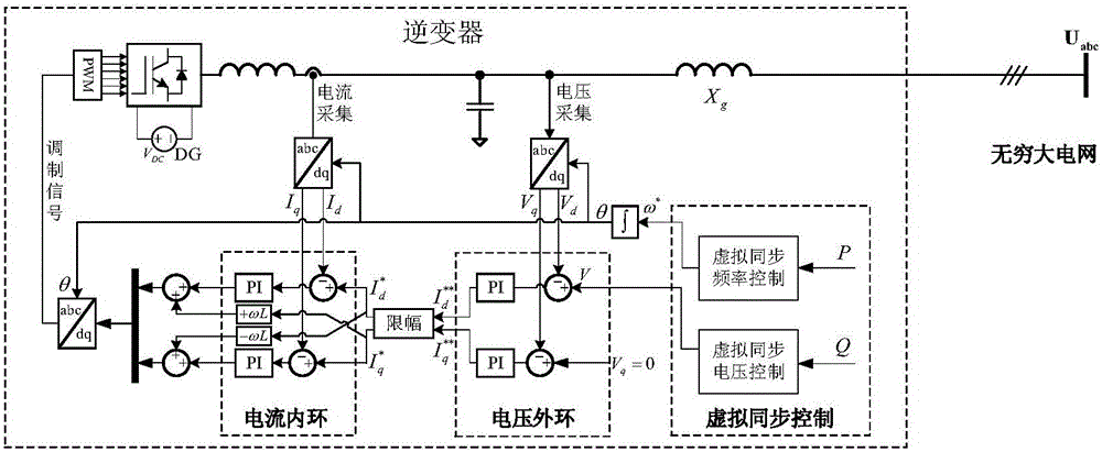
[0072] Incorporate an infinite system with a single inverter (such as figure 1 (shown) as an example, the single-machine infinite system is used for simulation, and the current adopts the d-axis current priority limiting method, and its limiting value is I max = 1.05, see Table 2 for other parameters used in the simulation. Inverter with P 0 =0.7p.u. start, the amplitude of the external voltage at t=2s Dropped from 1.0p.u. to 0.7p.u. and recovered to 1.0p.u. at t=8s, using the traditional virtual synchronous control (that is, the modified virtual synchronous equation is not used in the case of overcurrent) as the control group, the proposed improved inverter Effectiveness of Transient Control Methods for Synchronous Stability of Synchronous Devices.

[0073] Table 2 The parameter values ​​of some system variables in the simulation verification of the embodiment

[0074]

[0075]

[0076] Figure 5 Give the amplitude of the external voltage when t=2s From 1.0p.u. ...


PUM


Abstract

The invention discloses a transient control method for controlling the synchronous stability of a virtual synchronous control inverter. At present, the research on the stability of an inverter mainly focuses on the small-disturbance stability of an inverter in a micro grid. There is relatively less research on the transient stability under large disturbance, and the stability mechanism is unclear. In view of the virtual power angle instability caused by inverter current saturation, reactive power plus transient control are introduced into virtual synchronous control, so that an inverter has a reachable stable equilibrium point in the transient process of current saturation, and the synchronous stability of the inverter under large disturbance is ensured. The technical problem that there may be no stable equilibrium point in the transient process for the system due to saturation of the inner current loop of an inverter is solved. Transient instability of virtual power angle after an inverter goes to a current source mode is prevented.

Description

technical field [0001] The invention relates to a control method for a power grid virtual synchronous control inverter (referring to a virtual synchronous machine or a droop control inverter), in particular to a transient control method for improving the synchronization stability of a virtual synchronous control inverter. Background technique [0002] In recent years, with the rapid development of renewable energy such as wind power and photovoltaics, large-scale wind power and photovoltaic power stations with inverters as grid-connected interfaces have been established in China. Therefore, the stability of inverters is of great significance to the safe operation of power grids. . [0003] Virtual synchronous control (including virtual synchronous machine control and droop control) makes the inverter present the characteristics of a voltage source, which is widely used in practice, especially when new energy is connected to the microgrid or weak grid, the virtual synchronous...

Claims


Application Information

Patent Timeline
Patent Type & Authority Applications(China)
IPC IPC(8): H02J3/38
CPCH02J3/38
Inventor 吴跨宇辛焕海黄林彬黄晓明楼伯良卢岑岑陆海清卢嘉华熊鸿韬沈轶君房乐
Owner ELECTRIC POWER RES INST OF STATE GRID ZHEJIANG ELECTRIC POWER COMAPNY
Why Eureka
Try Eureka