
Thrust load measuring device for sealed mixing device and calibration method for same

A technology of axial load and measuring device, which is applied in the direction of measuring device, mixer with rotating stirring device, calibration/testing of force/torque/power measuring instrument, etc., which can solve the problems of large scale and complexity of measuring device

Inactive Publication Date: 2016-08-03
KOBE STEEL LTD
View PDF11 Cites 1 Cited by
  • Summary
  • Abstract
  • Description
  • Claims
  • Application Information

AI Technical Summary

Problems solved by technology

In such preliminary experiments, it is important to provide a mechanism that applies a large axial load to the rotor and a mechanism that rotates the rotor, and the measurement device itself becomes a large-scale and complicated structure.

Method used


Image

  • Thrust load measuring device for sealed mixing device and calibration method for same
  • Thrust load measuring device for sealed mixing device and calibration method for same
  • Thrust load measuring device for sealed mixing device and calibration method for same

Examples


Embodiment Construction

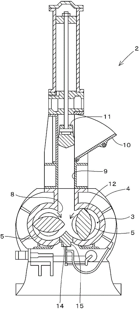
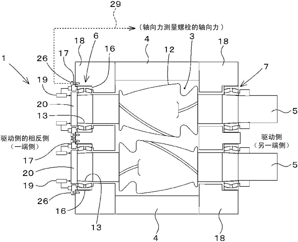
[0033]Hereinafter, the axial load measuring device 1 and its calibration method according to the embodiment of the present invention will be described. First, before describing the calibration method of the axial load measuring device 1 , the closed kneading apparatus 2 provided with the axial load measuring device 1 will be described. figure 1 The closed kneading device 2 of this embodiment is schematically shown. Such as figure 1 As shown, the closed kneading device 2 of the present embodiment includes a housing 4 having a kneading chamber 3 therein, and a pair of rotors 5 , 5 provided inside the housing 4 . Furthermore, the closed kneading device 2 uses a pair of rotors 5, 5 to knead the materials to be kneaded such as rubber and plastics that are pressed into the kneading chamber 3, and to knead the materials to be kneaded into a desired kneading state. A structure in which material is taken out.

[0034] Such as figure 2 As shown, the pair of rotors 5 , 5 are rotatab...


PUM


Abstract

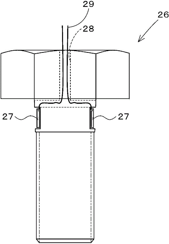
The relative displacement in the axial direction between an outer ring fixing member (17) or casing (18) and an inner ring fixing member (20) or rotor (5) is determined, said outer ring fixing member (17) being a member for affixing an outer ring (16) of a bearing (6) on one side, and said inner ring fixing member (20) being a member for affixing an inner ring (13) of the bearing (6) on the one end side. When calculating a thrust load acting on the rotor (5) by multiplying the determined relative displacement by a conversion coefficient, an axial force measuring bolt (26) is used as a tightening bolt for affixing the bearing (6) on the one end side, said axial force measuring bolt (26) enabling measurement of a load acting in the axial direction. The axial force measured by the axial force measuring bolt (26) and the relative displacement during measurement of the axial force are used to calibrate the conversion coefficient.

Description

technical field [0001] The present invention relates to an axial load measuring device and a correction method thereof for measuring the axial load generated by a rotor when a material to be kneaded is kneaded by a closed kneading device. Background technique [0002] Conventionally, there is a closed kneading device disclosed in Patent Document 1 as a closed kneading device for kneading materials to be kneaded such as rubber and plastics. The closed kneading device of Patent Document 1 adopts a structure in which two rotors provided in the kneading chamber are used to knead the materials to be kneaded that are pressed into the kneading chamber, and the materials to be kneaded into the desired kneading state are kneaded. The material to be kneaded is taken out to the outside. Both sides of the shafts of these two rotors are rotatably supported by bearings. The drive-side end of each rotor serves as an input shaft protruding outward. The output shafts of the driving device...

Claims


Application Information

Patent Timeline
Patent Type & Authority Applications(China)
IPC IPC(8): B01F15/00B01F7/08B29B7/18B29B7/28
CPCB29B7/183B29B7/246B29B7/263B29C48/252B29C48/2522B29B7/283G01L5/12G01L25/00B29B7/22B29B7/186B29B7/18B01F35/212
Inventor 冈田彻田中雄介
Owner KOBE STEEL LTD
Learn More