Pulse back-blowing soot cleaning device and its gas ejector and filter device

A technology of pulse back-blowing and dust-cleaning device, which is applied in the fields of pulse back-blowing and dust-cleaning devices and their gas ejectors and filter devices, and can solve problems such as poor anti-deformation ability, poor back-blowing effect of filter tubes, fatigue fracture of filter tubes, etc. Problems, reduce the impact of thermal shock and vibration, improve the air distribution, reduce the effect of blowback cleaning pressure

Inactive Publication Date: 2018-06-22
HENAN POLYTECHNIC UNIV
View PDF3 Cites 0 Cited by
  • Summary
  • Abstract
  • Description
  • Claims
  • Application Information

AI Technical Summary

Problems solved by technology

[0005] For the existing pulse blowback cleaning device, because the shape of the existing gas ejector is conical, the length of the "primary jet (that is, the amount of gas ejected from the nozzle)" when the nozzle is sprayed is limited, and the energy is concentrated In the position of the central axis, the blowback effect of the filter tube outside the central axis is poor
At the same time, the "primary jet" and "secondary jet (that is, the ejected gas volume of the surrounding gas ejected by the gas ejector)" are not uniform when mixed at the throat of the gas ejector, and the energy exchange and transfer efficiency is low, making During the backflushing process, the peak pressure in the filter tube is low, which affects the cleaning strength and cleaning efficiency, making the cleaning uneven and incomplete
In this case, due to the poor deformation resistance of the ceramic filter tube, the backflush pressure is mainly concentrated at the axial position, which makes the filter tube at the axial position prone to fatigue fracture, thus making the entire filter invalid.
[0006] It can be seen that the cleaning effect of the pulse back-blowing soot cleaning device in the prior art is relatively poor. The inventor has relied on years of experience and practice in related industries to propose a pulse back-blowing soot cleaning device for filters and its gas Ejectors to overcome existing technical deficiencies

Method used


Image

  • Pulse back-blowing soot cleaning device and its gas ejector and filter device
  • Pulse back-blowing soot cleaning device and its gas ejector and filter device
  • Pulse back-blowing soot cleaning device and its gas ejector and filter device

Examples


Embodiment Construction

[0023] In order to make the purpose, technical solution and advantages of the present invention clearer, the present invention will be further described in detail below in conjunction with the accompanying drawings and specific embodiments.

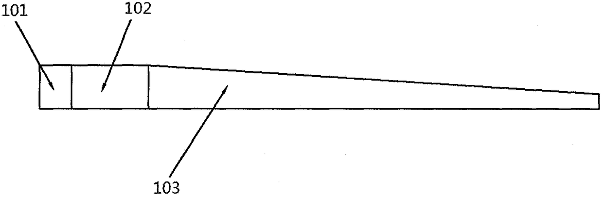
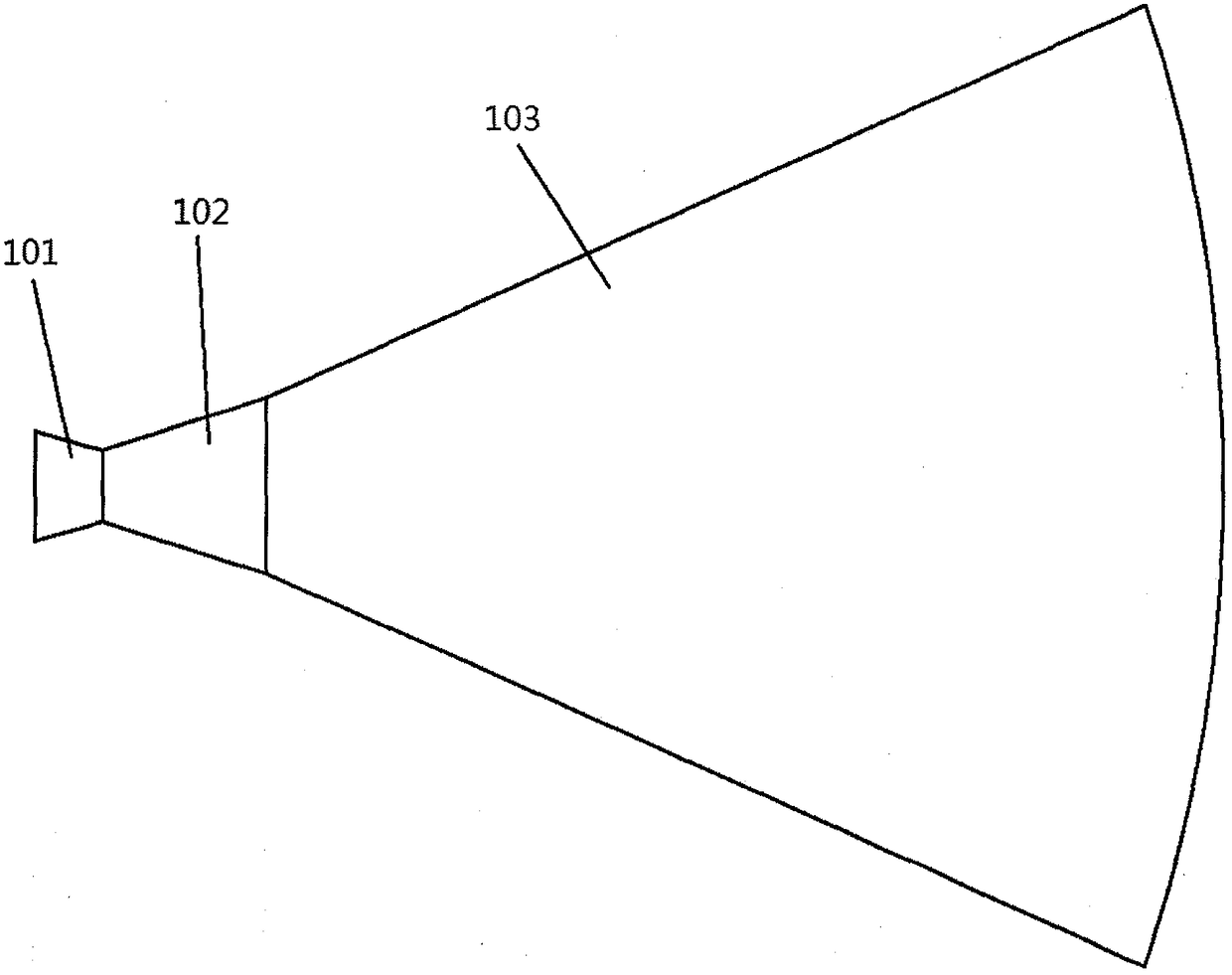
[0024] Figure 1a and 1b A gas ejector of a pulse back-blowing soot cleaning device provided by an embodiment of the present invention. The gas ejector includes an ejector body, and the ejector body includes an inlet portion 101, a neck portion 102 and an inclined portion 103 connected to each other in sequence, wherein the inlet portion 101, the neck portion 102, and the inclined portion 103 are longitudinally sectioned. gradually decreases in height ( Figure 1a The vertical direction shown is the height direction of the gas ejector); multiple output ports of the ejector body are arranged at the bottom of the inclined part, and each output port corresponds to an inlet of an external filter element.

[0025] In this way, the height of t...


PUM


Abstract

The invention provides a pulse back-blowing dust cleaning device, a gas ejector and a filter device thereof. The gas ejector used by the pulse back-blowing soot cleaning device and the filter device includes an ejector body, and the ejector body includes an inlet part, a neck and an inclined part connected to each other in sequence, and the inlet part, the neck The height of the longitudinal section of the slope and the inclined portion gradually decreases, and the gas ejector is arranged transversely relative to the filter tube of the filter device. By improving the shape of the gas ejector and its arrangement in the pulse back-blowing and dust-cleaning device, the back-blowing airflow can no longer be concentrated at the center, but the filter tubes corresponding to the gas ejector can be relatively smooth. Uniform backflushing enables the filter tube to be cleaned evenly and thoroughly. In this way, the pressure of back blowing and dust cleaning can be reduced, and the impact of back blowing gas on the thermal shock and vibration of the filter tube will also be reduced, prolonging the service life of the filter tube.

Description

technical field [0001] The invention belongs to the technical field of gas-solid separation, and relates to a filter device, in particular to a pulse back-blowing soot cleaning device in the filter device and a gas ejector thereof. Background technique [0002] High-temperature gas dedusting is a technology that directly separates gas from solid under high-temperature conditions to achieve gas purification. The ceramic filter used in the high-temperature gas dedusting process is recognized as the most promising high-temperature gas purification equipment, and has broad application prospects in clean coal combustion power generation, petroleum processing and environmental protection. [0003] When filtering, the dust particles in the gas deposit on the outer surface of the filter tube to form a filter cake, and the filtration pressure drop increases. It is necessary to periodically blow back through high-pressure gas pulses to remove the filter cake on the outer surface of th...

Claims


Application Information

Patent Timeline
Patent Type & Authority Patents(China)
IPC IPC(8): B01D46/42B01D46/24
CPCB01D46/24B01D46/42B01D46/72B01D46/71
Inventor 李海霞李宾林龙宋军高丙光白雪
Owner HENAN POLYTECHNIC UNIV
Why Eureka
Try Eureka