Intelligent lifting type forced road speed bump

A technology of lift-type and speed bumps, which is applied in the field of intelligent lift-type road speed bumps, can solve the problems of safety traffic accidents, reduced vehicle driving safety, and inability to adjust the height of obstacles, so as to ensure the safety of road vehicles and pedestrians, and is easy to install And maintenance, the effect of good speed limit warning effect

Active Publication Date: 2016-08-10
HUNAN UNIV OF SCI & TECH
View PDF4 Cites 16 Cited by
  • Summary
  • Abstract
  • Description
  • Claims
  • Application Information

AI Technical Summary

Problems solved by technology

At present, the road speed bumps used in China, some speed bumps have the obstacle height set too low. Although they can play a certain role in speed limit warning, it is difficult for people who lack the awareness of safe driving to achieve the purpose of substantive deceleration. Too fast will lead to safety traffic accidents; while the obstacle height of some speed bumps is set too high and cannot be adjusted, once it is fixed and installed, the height of the obstacles cannot be adjusted. For vehicles passing by at low speed, it will also reduce the driver's driving safety and riding comfort expectations, because the strong transient vibration shock will reduce the comfort of the driver and passengers, and reduce the driving safety of the vehicle. less sense of security
Moreover, this kind of vibration and shock can easily cause fatigue damage to the mechanical parts structure and electronic components of the passing vehicle, and even cause a safety traffic accident due to functional failure.

Method used


Image

  • Intelligent lifting type forced road speed bump
  • Intelligent lifting type forced road speed bump
  • Intelligent lifting type forced road speed bump

Examples


Embodiment Construction

[0015] The present invention will be further described below in conjunction with the accompanying drawings.

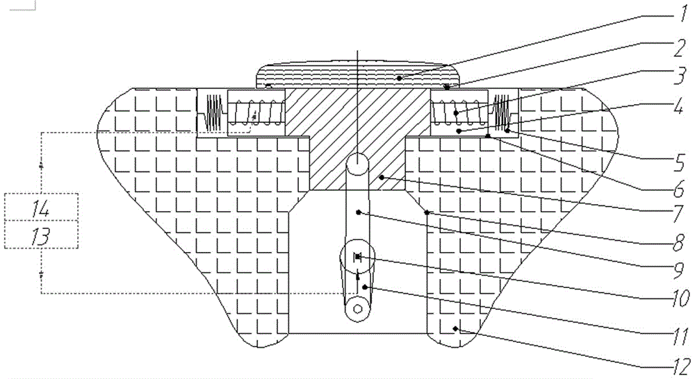
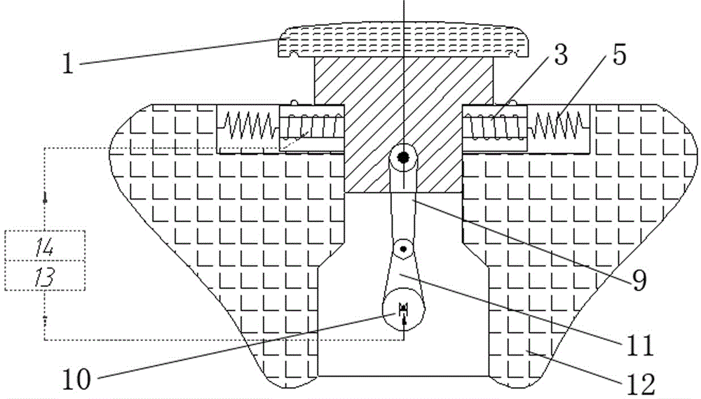
[0016] Such as Figure 1-4 As shown, the vehicle speed intelligent detection and judgment system 13 of the present invention, the lifting drive device, the stepped lifting platform, the double slider limit device, and the power supply module 14. The lifting drive device includes a connecting rod 9 , a crank 11 , a drive motor 10 and a protective case 8 . The output shaft of the drive motor 10 is provided with a crank 11, the end of the crank 11 is hinged with one end of the connecting rod 9, and the other end of the connecting rod 9 is hinged with the stepped lifting platform. The drive motor 10 and the crank 11 are located inside the protective case 8 . The drive motor 10 is used to drive the stepped lifting platform 7; the protective shell 8 is used to provide an independent space for the crank type motor drive device under the ground to avoid water leakage. The l...


PUM


Abstract

The invention discloses an intelligent lifting type forced road speed bump. The forced road speed bump comprises an intelligent vehicle speed detecting and judging system, a power supply module, a lifting drive device, a step-shaped iron lifting platform, two sliding blocks, two springs and two protective cylinder sleeves, wherein the lifting drive device is connected with the step-shaped iron lifting table and controls lifting of the step-shaped iron lifting platform; the two sliding blocks are mounted on two sides of the upper part of the step-shaped iron lifting platform respectively, energized spiral armatures are arranged in the sliding blocks, and the two sliding blocks are connected with the two protective cylinder sleeves through the springs respectively; the energized spiral armatures and the lifting drive device are connected with the intelligent vehicle speed detecting and judging system respectively; the intelligent vehicle speed detecting and judging system is connected with the power supply module. The vertical barrier height of the speed bump is controlled through two times of intelligent detection and judgment of vehicle speed, forced speed reduction and warning are performed on overspeed vehicles, the safety and the taking comfort of running vehicles based on speed limit regulations are guaranteed, and potential safety hazards caused by traffic disturbance in person and vehicle mixed road sections and particularly vehicles' violation of speed-limit standards are prevented.

Description

technical field [0001] The invention belongs to the field of road traffic safety facilities, and in particular relates to an intelligent lifting type road compulsory deceleration belt. Background technique [0002] The intelligent lift-type road speed bump is a kind of road traffic infrastructure special facility that combines mechanical, electronic, magnetic and other technologies to ensure the safety of pedestrians and vehicles. It can be widely used in industrial and mining enterprises, schools, squares, pedestrian streets, entrances to residential quarters, Public parking lots and other road sections with heavy vehicle traffic and slow speed limit and road sections that are likely to cause traffic accidents. Because these places often have a large flow of vehicles, trucks, motorcycles, electric vehicles, bicycles and other vehicles, and also include pedestrians such as the elderly, children, pregnant women, and disabled people, it is easy to form a special phenomenon of ...

Claims


Application Information

Patent Timeline
Patent Type & Authority Applications(China)
IPC IPC(8): E01F9/529
Inventor 宾光富王俊周剑郑海祥胡亮郭帅平李学军
Owner HUNAN UNIV OF SCI & TECH
Why Eureka
Try Eureka