A camera power consumption control method and mobile terminal
A mobile terminal, power consumption control technology, applied in image communication, TV, color TV components and other directions, can solve problems affecting user experience, improve user experience, solve excessive power consumption, and increase standby time. Effect
- Summary
- Abstract
- Description
- Claims
- Application Information
AI Technical Summary
Problems solved by technology
Method used
Image
Examples
no. 1 example
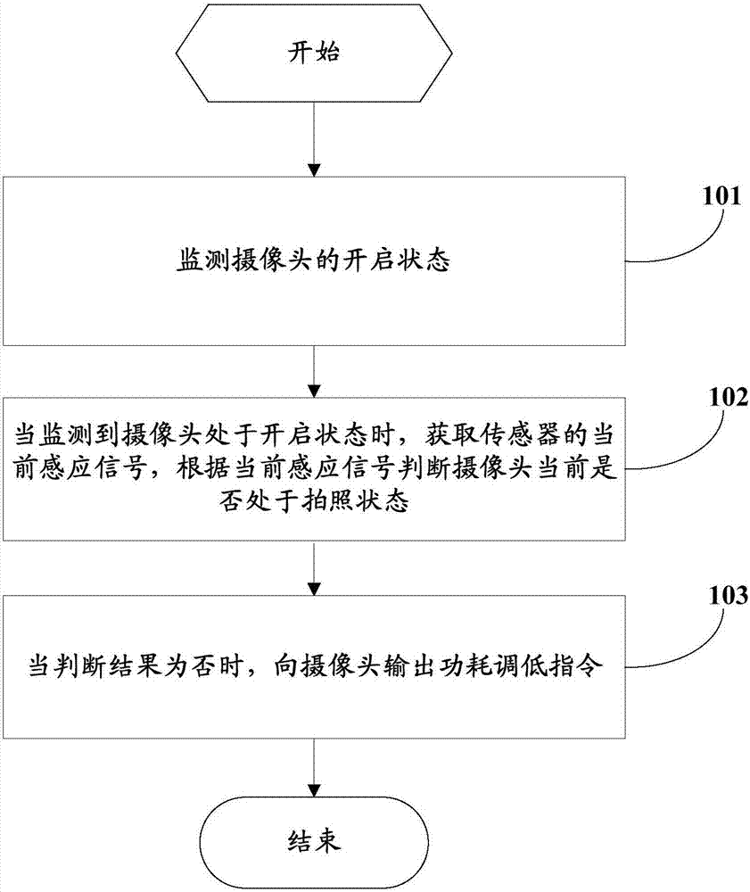
[0025] see figure 1 , the first embodiment of the present invention provides a method for controlling power consumption of a camera, which is applied to a mobile terminal, wherein the mobile terminal may be a smart phone or a tablet computer, etc.; the mobile terminal includes multiple sensor, the power consumption control method of the camera includes:
[0026] Step 101, monitoring the opening state of the camera.
[0027] Specifically, the camera may be a front-facing camera or a rear-facing camera; the enabled state of the camera may be determined by detecting that the user turns on the camera or calling a camera function through other applications.
[0028] Step 102, when it is detected that the camera is in the open state, obtain the current sensing signal of the sensor, and judge whether the camera is currently in the photographing state according to the current sensing signal;
[0029] Under normal circumstances, users will have many scenes where the camera is turned ...
no. 2 example
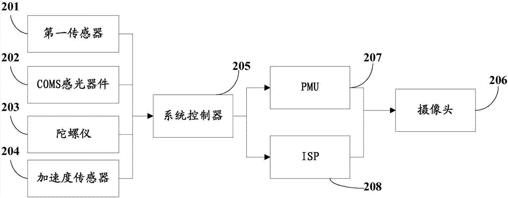
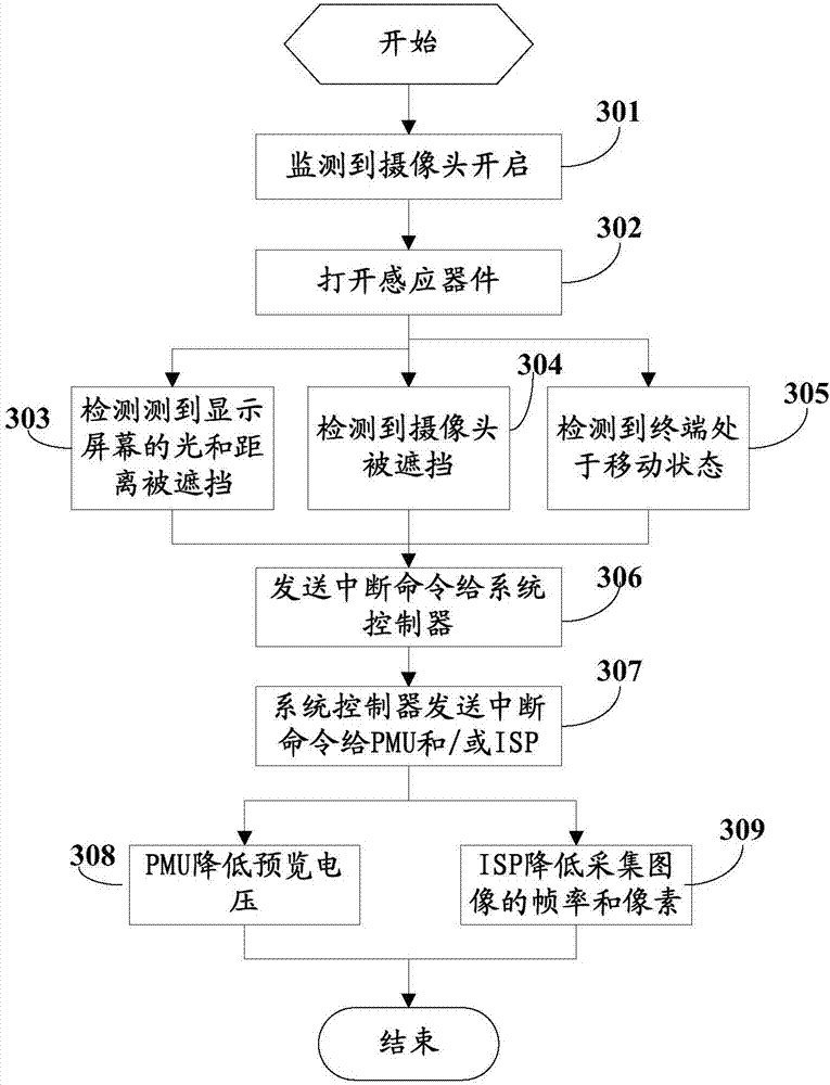
[0062] The second embodiment is used as a specific embodiment below to introduce the camera power consumption control method and the mobile terminal provided by the present invention. see figure 2 , figure 2 The block diagram of the mobile terminal provided for the second embodiment. Wherein, the mobile terminal includes: a first sensor 201, a CMOS light sensor 202, a gyroscope 203, an acceleration sensor 204, a system controller 205, a camera 206, a power management unit (PMU) 207 and / or an image signal processing unit (ISP) 208 ;
[0063] Among them, the first sensor 201 is arranged on the end face where the display screen is located, and is mainly used to detect the scene where the front of the mobile terminal is blocked, that is, the scene where the display screen is blocked, and when it detects that the display screen is blocked, an interrupt command is sent to the system control device 205.
[0064] The CMOS light sensor 202 is arranged on the camera 206, and is us...
no. 3 example
[0089] see Figure 5 , a block diagram of the mobile terminal provided by the third embodiment of the present invention, Figure 5 The mobile terminal 500 shown includes a plurality of sensors for detecting the current use scene of the mobile terminal, and the mobile terminal 500 also includes: a monitoring module 501, an acquisition module 502 and a power consumption reduction module 503, wherein the monitoring module 501 and the acquisition module 502 is connected, and the acquisition module 502 is connected with the power consumption reduction module 503 .
[0090] Wherein, the monitoring module 501 is used for monitoring the opening state of the camera.
[0091]Specifically, the camera may be a front-facing camera or a rear-facing camera; the enabled state of the camera may be determined by detecting that the user turns on the camera or calling a camera function through other applications.
[0092] The acquiring module 502 is configured to acquire the current sensing sig...
PUM
 Abstract
Description
Claims
Application Information
 - R&D
- Intellectual Property
- Life Sciences
- Materials
- Tech Scout
- Unparalleled Data Quality
- Higher Quality Content
- 60% Fewer Hallucinations
Browse by: Latest US Patents, China's latest patents, Technical Efficacy Thesaurus, Application Domain, Technology Topic, Popular Technical Reports.
© 2025 PatSnap. All rights reserved.Legal|Privacy policy|Modern Slavery Act Transparency Statement|Sitemap|About US| Contact US: help@patsnap.com


