Water collecting device used in garden

A water collection device and gardening technology, applied in watering devices, gardening, applications, etc., can solve the problems of garden drainage burden, etc., and achieve the effects of ensuring work stability, convenient maintenance, and improving practicability

Inactive Publication Date: 2016-08-17
石鸿娟
View PDF1 Cites 0 Cited by
  • Summary
  • Abstract
  • Description
  • Claims
  • Application Information

AI Technical Summary

Problems solved by technology

However, there is still a problem with this irrigation system: the volume of the water storage device is fixed. When there is a heavy rain, the inner cavity of the water storage device will be filled instantly and overflow through the collection plate, which will cause a burden on the drainage of the garden.

Method used


Image

  • Water collecting device used in garden
  • Water collecting device used in garden

Examples


Embodiment 1

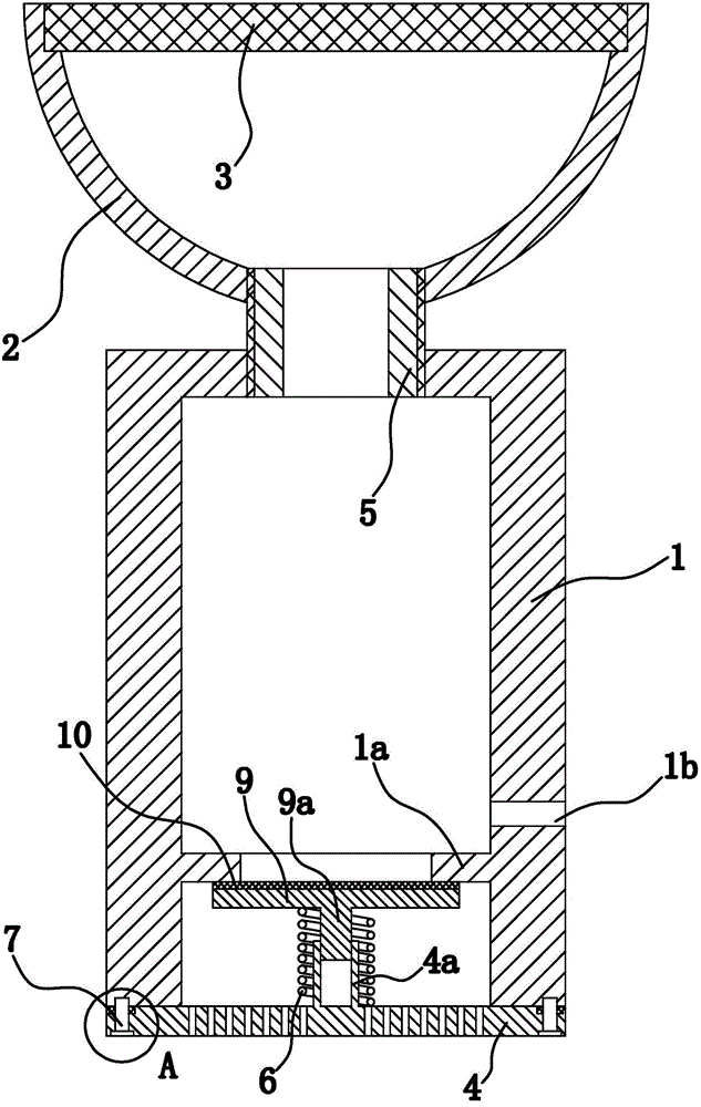
[0024] as shown in the picture 1 As shown, the garden water collection device consists of a cylinder 1 , collection bowl 2 ,Filter 3 , seals, filter plates 4 and so on.

[0025] Among them, the cylinder 1 It is cylindrical, and in actual installation, the entire cylinder 1 Set vertically underground. collection bowl 2 In the shape of a bowl, the collection bowl 2 placed in the cylinder 1 top with its opening facing upwards. collection bowl 2 The lumen of the 5 with cylinder 1 The inner cavity at the upper end communicates. Specifically, the collection bowl 2 There are threaded holes through the bottom of the cylinder, 1 The inner side of the upper end has a threaded section, and the connecting pipe 5 The two ends of the threaded structure and the collection bowl are respectively passed 2 and cylinder 1 Sealed and fixed. as shown in the picture 1 shown, collection bowl 2 There are ring-shaped steps on the inner wa...

Embodiment 2

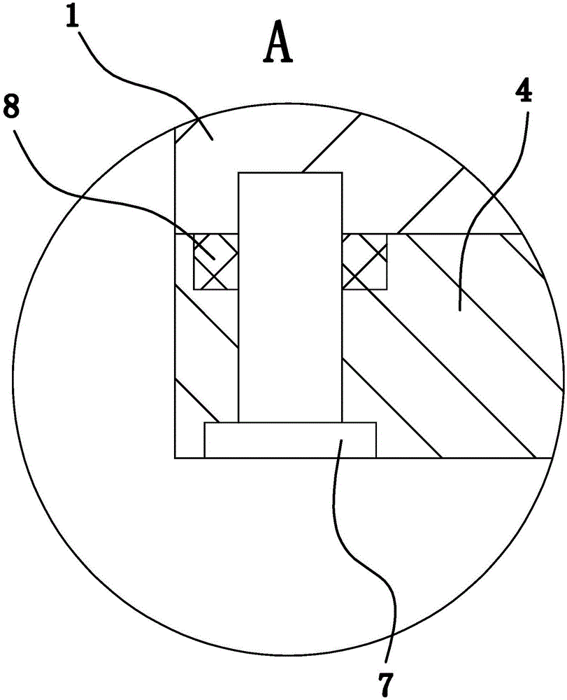
[0031] The structure and principle of this second embodiment are basically the same as that of the first embodiment, except that the sealing member includes a support plate, and the upper side of the support plate has a cylindrically protruding sealing portion, and the sealing portion is inserted into the annular shoulder 1a Inside, the side wall of the sealing part is provided with an annular sealing groove, and the annular sealing groove is provided with 0 ring, and 0 The outer peripheral surface of the ring and the annular shoulder 1a The inner wall is offset.


PUM


Abstract

The invention provides a water collecting device used in a garden. The problem that an existing garden rainwater collecting device is single in function is solved. The water collecting device used in the garden comprises a cylinder and a collecting bowl arranged at the top of the cylinder, wherein the collecting bowl is communicated with the upper end of the cylinder through a connecting pipe, a filter screen is arranged in the collecting bowl, a filter plate is arranged at the bottom of the cylinder, the upper end face of the filter plate abuts against the lower end face of the cylinder, the filter plate is detachably fixed to the cylinder, an annular groove is formed in the edge position of the upper end face of the filter plate, an annular sealing pad is arranged in the annular groove, and two end faces of the annular sealing pad respectively abut against the bottom wall of the annular groove and the lower end face of the cylinder. An annular blocking shoulder is arranged on the inner side wall of the cylinder, a sealing part capable of sliding in the axial direction of the cylinder and a spring enabling the sealing part to be about to seal a lower port of the annular blocking shoulder are arranged in the cylinder, and a water outlet is formed in the side wall of the cylinder and located above the annular blocking shoulder. The water collecting device used in the garden has the advantages of having water storage and water discharging functions.

Description

technical field [0001] The invention relates to garden equipment, in particular to a garden water collection device. Background technique [0002] Most of the current garden irrigation is basically done by manpower, resulting in higher irrigation costs. [0003] For the above problems, people have realized the shortcomings and made improvements, such as a garden automatic irrigation system [application number: 201520215648.0; authorization announcement number: CN 204579352 U] disclosed in the Chinese patent library, including a rainwater collector, a Water storage device, a delivery device and a micro-irrigation device, the water storage device is buried underground, the rainwater collector is fixed above the water storage device, and the delivery device is connected to the water storage device and the water storage device respectively. The micro-irrigation device, the delivery device is also sequentially connected to a water inlet valve and a water pipe, the water pipe is ...

Claims


Application Information

Patent Timeline
Patent Type & Authority Applications(China)
IPC IPC(8): A01G25/00
CPCA01G25/00
Inventor 石鸿娟
Owner 石鸿娟
Why Eureka
Try Eureka