Laminated test tube apparatus convenient for placing test tubes

A layered, test tube technology, applied in the direction of test tube racks/clamps, laboratory equipment, chemical instruments and methods, etc., can solve the problems of multiple test tube racks and occupying space on the test bench, and achieve easy operation, simple structure, and save experiments The effect of table space

Inactive Publication Date: 2016-08-17
CHENGDU EMPEROR MEDICAL TECH CO LTD
View PDF5 Cites 1 Cited by
  • Summary
  • Abstract
  • Description
  • Claims
  • Application Information

AI Technical Summary

Problems solved by technology

[0005] The technical problem to be solved by the present invention is: the existing test tube rack can only place one layer of test tubes, and the problem that multiple test tube racks occupy the space of the test bench
Now we provide a stacked test tube device that is convenient for placing test tubes. The test tubes are arranged in a stacked manner, which solves the problem of requiring multiple test tube racks and occupying space on the test bench when placing test tubes.

Method used


Image

  • Laminated test tube apparatus convenient for placing test tubes
  • Laminated test tube apparatus convenient for placing test tubes

Examples


Embodiment 1

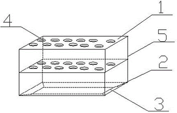
[0022] Such as figure 1 , figure 2 As shown, a stacked test tube device that is convenient for placing test tubes includes a top plate 1, a bottom plate 2, and a middle plate. The four corners of the bottom plate 2 are all provided with connecting parts, between the connecting parts of the top plate 1 and the connecting parts of the middle plate, between the connecting parts of the middle plate and the connecting parts of the bottom plate 2, are all connected by connecting rods 5; It is a cylindrical cavity, and the middle part of the connection part is provided with a partition.

[0023] In this embodiment, the top plate 1 and the middle plate are cuboid plates with a certain thickness, and the top plate 1 and the middle plate are all provided with through holes for placing test tubes, and the top plate 1, the middle plate, and the bottom plate 2 are arranged from top to bottom. Arranged in layers, the top board 1 and the middle board, the middle board and the bottom board...

Embodiment 2

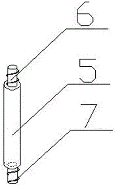
[0026] This embodiment is further defined on the basis of the above embodiments, the two ends of the partition are respectively a first cavity and a second cavity, and internal threads are provided in the first cavity and the second cavity. Both ends of the connecting rod 5 are provided with a first cylindrical rod 6 and a second cylindrical rod 7 respectively, and the first cylindrical rod 6 and the second cylindrical rod 7 are both provided with external threads. Here, the connection mode between the top plate 1 and the middle plate, between the middle plates, and between the middle plate and the bottom plate 2 is specifically limited, and the connection mode of thread adaptation is used to improve the stability of the test tube rack.

Embodiment 3

[0028] On the basis of the above-mentioned embodiments, this embodiment further defines that the top plate 1 and the middle plate are provided with through holes 4, and the center of the through hole on the top plate 1 is at the same center as the center of the through hole on the middle plate. vertical line. When placing, it can be inserted directly from the through hole 4 of the top plate 1 into the through hole at the corresponding position of the middle plate or from the through hole of the middle plate into the through hole at the corresponding position of the bottom plate 2 . Therefore, a stacked arrangement can be realized as required.


PUM


Abstract

The invention discloses a laminated test tube apparatus convenient for placing test tubes. The apparatus comprises a top board, a baseboard and a middle board which are sequentially arranged in a laminated manner from top to bottom, the four corners of each of the top board, the baseboard and the middle board are provided with connecting portions, the connecting portions of the top board are connected with the connecting portions of the middle board through connecting rods, and the connecting portions of the middle board are connected with the connecting portions of the baseboard through connecting rods; and the connecting portions are cylindrical cavities, and the middle portion of every connecting portions is provided with a separator board. The top board, the middle board and the baseboard can be arranged in a laminated manner, the quantity of the middle board can be one or above, the middle board, the top board and the baseboard are respectively provided with through holes for placing test tubes, and the test tube apparatus can be designed to have a multilayer structure as needed in order to realize placement of a large amount of test tubes.

Description

technical field [0001] The invention relates to medical instruments and equipment, in particular to a stacked test tube device which is convenient for placing test tubes. Background technique [0002] The test tube rack in the inspection center is the most basic laboratory instrument for placing and drying test tubes. It is often used to place test tubes for easy observation of experimental phenomena, and it can also be used to dry test tubes upside down. Existing test tube racks are generally made of wood or bamboo, and are generally these two kinds of 6 holes and 12 holes. [0003] In addition, the existing test tube rack structure can only place one layer of test tubes. When multiple test tubes are needed in the experiment, multiple test tube racks are needed. The space of table, and also extremely inconvenient for placing test tube. [0004] Based on this research, experimental operation analysts developed a stacked test tube device that facilitates the placement of t...

Claims


Application Information

Patent Timeline
Patent Type & Authority Applications(China)
IPC IPC(8): B01L9/06
CPCB01L9/06B01L2300/0887
Inventor 舒雄
Owner CHENGDU EMPEROR MEDICAL TECH CO LTD
Why Eureka
Try Eureka