Die device for stamping molding of steel plate

A stamping forming and steel plate technology, which is applied in the direction of forming tools, storage devices, feeding devices, etc., can solve the problems of troublesome installation of positioning mechanisms, many parts, troublesome installation and disassembly, etc., to improve the production effect, accurate installation and positioning, installation and disassembly convenient effect

Inactive Publication Date: 2016-08-17
青岛鑫精诚精密科技有限公司
View PDF7 Cites 9 Cited by
  • Summary
  • Abstract
  • Description
  • Claims
  • Application Information

AI Technical Summary

Problems solved by technology

[0002] When the existing thin and small-area steel plates are stamped and formed, the mold forming equipment used is generally large in size and has many parts, which makes the energy consumption of stamping production large and wasteful. For fixing, it is troublesome to install and disassemble
[0003] Moreover, positioning is required when the steel plate is fixed on the lower mold, and the existing positioning mechanism is troublesome to install

Method used


Image

  • Die device for stamping molding of steel plate

Examples


Embodiment

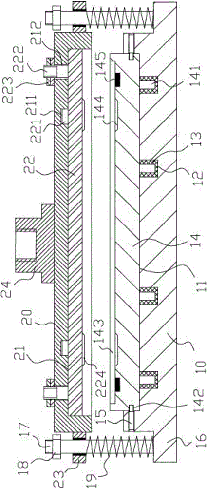
[0014] Example: see figure 1 As shown, a mold device for stamping and forming of a steel plate comprises a lower die connecting block 10 and a connecting plate 20, the middle part of the top surface of the lower die connecting block 10 has a lower die fixing groove 11, and the bottom surface of the lower die fixing groove 11 There are a plurality of positioning jacks 12, a strong magnet sleeve 13 is inserted into the positioning jack 12, the outer wall of the strong magnet sleeve 13 is fixed on the inner wall of the positioning jack 12, and the lower mold 14 is inserted into the lower mold fixing groove 11 Among them, the bottom surface of the lower mold 14 has a plurality of inserting rods 141, the inserting rods 141 are inserted into the strong magnet sleeve 13 and adsorbed in the strong magnet sleeve 13, and the screw holes on the inner side wall of the lower mold fixing groove 11 The middle screw is connected with a plurality of positioning studs 15, and the ends of the po...


PUM


Abstract

The invention discloses a die device for stamping molding of a steel plate. The die device comprises a lower die connection block and a connection plate, wherein a lower die fixing groove is formed in the middle of the top surface of the lower die connection block; a plurality of positioning inserting holes are formed in the bottom surface of the lower die fixing groove; strong magnet sleeves are inserted into the positioning inserting holes in a sleeving manner; outer side walls of the strong magnet sleeves are fixed on inner side walls of the positioning inserting holes; a lower die is inserted into a lower die fixing groove in the sleeving manner; a plurality of inserting rods are arranged on the bottom surface of the lower die; the inserting rods are inserted into the strong magnet sleeves in the sleeving manner and are adsorbed in the strong magnet sleeves; screw jointing through holes formed in the inner side wall of the lower die fixing groove are internally connected with a plurality of positioning studs in a screw jointing manner; the end parts of the positioning studs are inserted into side wall concave holes formed in the outer side wall of the lower die in the sleeving manner; an upper die mounting groove is formed in the middle of the bottom surface of a connection plate; and an upper die is inserted into an upper die mounting groove in the sleeving manner and is fixed on the top surface of the upper die mounting groove, and the upper die is located just above the lower die. The die device is simple in structure and small in size, the lower die is convenient to mount and detach, and the steel plate is accurately mounted and positioned so that the manufacturing effect is greatly improved.

Description

Technical field: [0001] The invention relates to the technical field of metal parts processing equipment, and more specifically relates to a die device for stamping and forming of steel plates. Background technique: [0002] When the existing thin and small-area steel plates are stamped and formed, the mold forming equipment used is generally large in size and has many parts, which makes the energy consumption of stamping production large and wasteful. For fixing, it is troublesome to install and disassemble. [0003] Moreover, positioning is required when the steel plate is fixed on the lower mold, and the installation of the existing positioning mechanism is troublesome. Invention content: [0004] The purpose of the present invention is to provide a die device for stamping and forming of steel plate, which is simple in structure, small in size, easy to install and disassemble the lower die, accurate and convenient to install and position the steel plate, and greatly im...

Claims


Application Information

Patent Timeline
Patent Type & Authority Applications(China)
IPC IPC(8): B21D37/10B21D43/00
CPCB21D37/10B21D43/003
Inventor 付淑珍
Owner 青岛鑫精诚精密科技有限公司
Why Eureka
Try Eureka