
Three-point positioning mechanism for plastic cylinder

A technology of three-point positioning and cylindrical body, which is applied in metal processing and other directions, can solve problems such as troublesome, no clamping device, etc., and achieve the effect of good effect, firm clamping and fixing, and convenient connection

Active Publication Date: 2016-08-17
太仓意欣智能科技有限公司
View PDF6 Cites 21 Cited by
  • Summary
  • Abstract
  • Description
  • Claims
  • Application Information

AI Technical Summary

Problems solved by technology

[0002] When the existing cylindrical plastic products need to groove or dig holes in their side walls, they need to use equipment to clamp the cylinder body, but now there is no specific clamping device, which generally uses two screw screws Connected to the support plate, through the rotation of two screws, the clamp blocks fixed at the ends of the two screws clamp and fix the cylinder, and then cut manually, which is very troublesome

Method used


Image

  • Three-point positioning mechanism for plastic cylinder
  • Three-point positioning mechanism for plastic cylinder
  • Three-point positioning mechanism for plastic cylinder

Examples


Embodiment

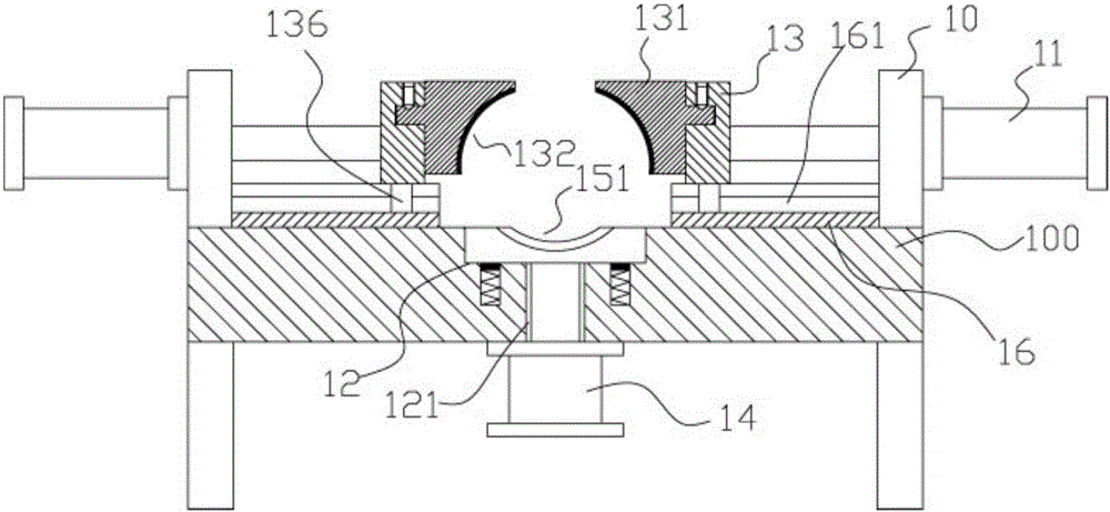
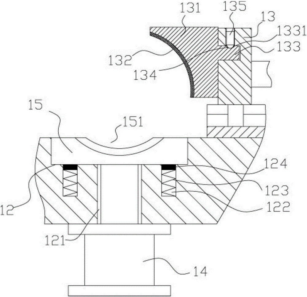
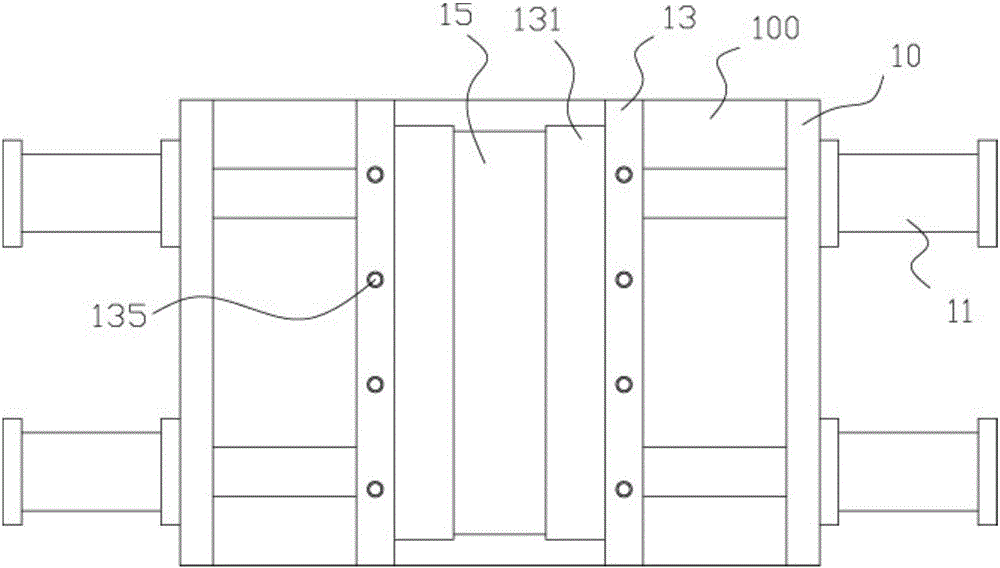
[0016] Example: see Figure 1 to Figure 4 As shown, a plastic cylinder three-point positioning mechanism includes a frame 100, an upper support plate 10 is fixed on the top surface of both sides of the top plate of the frame 100, and at least two Two clamping cylinders 11, the push rods of two clamping cylinders 11 pass through the upper support plate 10, the ends of the push rods of clamping cylinders 11 are fixed with connecting plates 13, and the opposite faces of the two connecting plates 13 are fixed with The clamping blocks 131 have arc-shaped grooves 132 on the opposite walls of the two clamping blocks 131;

[0017] The middle part of the top surface of the top plate of the frame 100 has a connection groove 12, and the top surface of the connection groove 12 has a telescopic through hole 121. The bottom surface of the top plate of the frame 100 is fixed with a lifting cylinder 14, and the push rod of the lifting cylinder 14 The end passes through the telescopic through...


PUM


Abstract

The invention discloses a three-point positioning mechanism for a plastic cylinder. The three-point positioning mechanism comprises a rack. Upper supporting plates are fixed to the top faces of the two sides of a top plate of the rack. At least two clamping cylinders are fixed to the outer side walls of the upper supporting plates. Push rods of the two clamping cylinders penetrate through the corresponding upper supporting plates, and connecting plates are fixed to the ends of the push rods of the clamping cylinders. Clamping blocks are fixed to opposite faces of the two connecting plates, and arc grooves are formed in the opposite walls of the two clamping blocks. A connecting groove is formed in the middle of the top face of the top plate of the rack, an expandable through hole is formed in the top face of the connecting groove, and a lifting cylinder is fixed to the bottom face of the top plate of the rack. The plastic cylinder is automatically clamped in a three-point positioned mode through the two arc grooves and the upper arc groove by adopting the clamping cylinders and the lifting cylinder, the plastic cylinder is fixedly and firmly clamped, and the effect is good; meanwhile, the clamping blocks are convenient to connect and mount and also convenient to dismount and replace.

Description

Technical field: [0001] The invention relates to the technical field of plastic processing equipment, and more specifically relates to a three-point positioning mechanism for a plastic cylinder. Background technique: [0002] When the existing cylindrical plastic products need to groove or dig holes in their side walls, they need to use equipment to clamp the cylinder body, but now there is no specific clamping device, which generally uses two screw screws Connected to the support plate, rotate the two screw rods, fix the clamping blocks at the ends of the two screw rods to clamp and fix the cylindrical body, and then manually cut it, which is very troublesome. Invention content: [0003] The purpose of the present invention is to provide a three-point positioning mechanism for a plastic cylinder in view of the deficiencies in the prior art, which uses a clamping cylinder and a lifting cylinder to automatically position three-point positioning through two arc-shaped groove...

Claims


Application Information

Patent Timeline
IPC IPC(8): B26D7/02
CPCB26D7/02
Inventor 付淑珍
Owner 太仓意欣智能科技有限公司
Learn More