Method for operating a fuel injector

A technique for jet valves and operating characteristics, applied in the field of operating jet valves, to achieve the effect of short interval time and low precision requirements

Active Publication Date: 2016-08-17
ROBERT BOSCH GMBH
View PDF5 Cites 6 Cited by
  • Summary
  • Abstract
  • Description
  • Claims
  • Application Information

AI Technical Summary

Problems solved by technology

This is especially disadvantageous for multiple injections with short intervals between individual injections

Method used


Image

  • Method for operating a fuel injector
  • Method for operating a fuel injector
  • Method for operating a fuel injector

Examples


Embodiment Construction

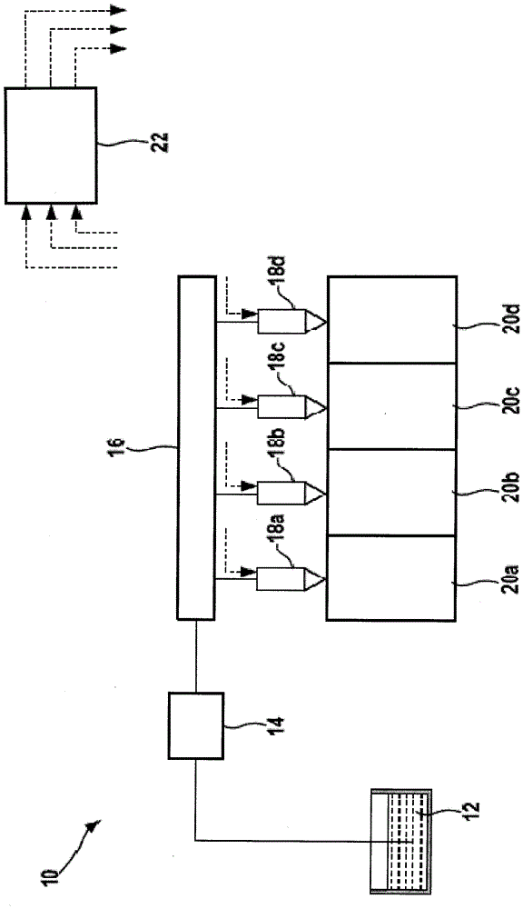
[0023] internal combustion engine in figure 1 The center bears the reference numeral 10 as a whole. It includes a fuel tank 12 from which a delivery system 14 delivers fuel into a common rail 16 . A plurality of electromagnetically actuated injection valves 18a to 18d are connected to this common rail, which inject fuel directly into the combustion chambers 20a to 20d assigned to them. The operation of internal combustion engine 10 is controlled or regulated by a control and regulating device 22 which, in particular, also actuates injection valves 18a to 18d.

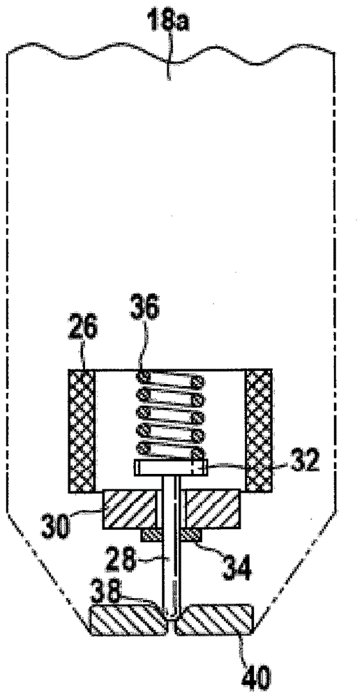
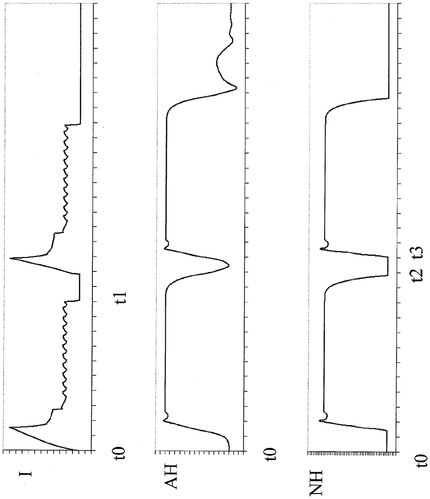
[0024] Figures 2a to 2c schematically illustrate the following figure 1 Injection valve 18a in a total of three different operating states. other in figure 1 The injection valves 18b, 18c, 18d depicted in have a corresponding structure and function.

[0025] Injection valve 18 a has an electromagnetic actuator having a solenoid coil 26 and an armature 30 interacting with solenoid coil 26 . The armature 30 is conne...


PUM


Abstract

A method for operating a fuel injector, in particular of an internal combustion engine, is described. At least one first injection and one second injection take place in succession. A valve needle reaches its closed position at a first point in time. The triggering of the second injection begins at the first point in time.

Description

technical field [0001] The invention relates to a method of the type according to independent claim 1 . A computer program, a machine-readable storage medium, a control device and a program code are also subjects of the invention. Background technique [0002] A method for operating an injection valve is already known from DE 10 2009 002 483 A1. There, a method is described in which the valve needle is driven by means of an electromagnetic actuator. A variable characterizing the acceleration of an armature of the electromagnetic actuator is formed as a function of at least one electrical operating characteristic variable of the electromagnetic actuator. The operating state of the injector is deduced from this variable characterizing the acceleration. [0003] In the injection valve shown there, the armature is not fixedly connected to the valve needle, but is mounted floating between two stops. [0004] The axial play between the armature and the two stops is referred to...

Claims


Application Information

Patent Timeline
Patent Type & Authority Applications(China)
IPC IPC(8): F02D41/20F02D41/40F02D28/00
CPCF02D28/00F02D41/2096F02D41/40F02D41/401F02D2041/2058F02D2041/2055F02D2041/2051F02M51/0653F02M51/0607F02D41/20F02D41/402F02D2041/2037F02M51/06Y02T10/40F02M61/18
Inventor M.伯A.沙德M.鲍尔
Owner ROBERT BOSCH GMBH
Why Eureka
Try Eureka