
Visualization tracking method and apparatus

An object and starting point technology, applied in the field of target object tracking, can solve the problems that it is difficult for monitors to understand intuitively and cannot be visually tracked by tracked objects.

Active Publication Date: 2016-08-17
STATE GRID BEIJING ELECTRIC POWER +1
View PDF3 Cites 5 Cited by
  • Summary
  • Abstract
  • Description
  • Claims
  • Application Information

AI Technical Summary

Problems solved by technology

[0005] Embodiments of the present invention provide a visual tracking method and device to at least solve the technical problem in the related art that it is difficult for monitoring personnel to intuitively understand the actual running track of the object due to the inability to visually track the tracked object.

Method used


Image

  • Visualization tracking method and apparatus
  • Visualization tracking method and apparatus

Examples


Embodiment 1

[0023] According to an embodiment of the present invention, a method embodiment of a visual tracking method is provided. It should be noted that the steps shown in the flowcharts of the accompanying drawings may be performed in a computer system, such as a set of computer-executable instructions, and that although a logical order is shown in the flowcharts, in some cases, The steps shown or described may be performed in an order different than here.

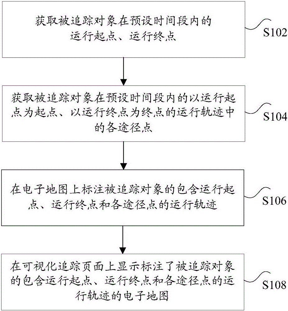
[0024] figure 1 is a flowchart of an optional visual tracking method according to an embodiment of the present invention, such as figure 1 As shown, the method includes the following steps:

[0025] Step S102, obtaining the running start point and running end point of the tracked object within a preset time period;

[0026] Step S104, acquiring each passing point in the running trajectory of the tracked object starting from the starting point of the running and ending at the ending point of the running within the preset time p...

Embodiment 2

[0052] According to an embodiment of the present invention, a device embodiment of a visual tracking device is provided.

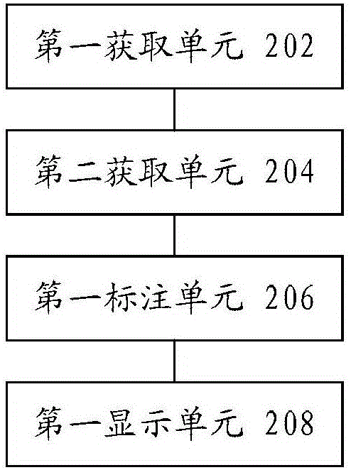
[0053] figure 2 is a schematic diagram of an optional visual tracking device according to an embodiment of the present invention, such as figure 2 As shown, the device includes: a first acquisition unit 202, used to acquire the running start point and running end point of the tracked object within a preset time period; a second acquisition unit 204, used to acquire the tracked object within a preset time period Each passing point in the running trajectory with the starting point as the starting point and the ending point as the ending point; the first labeling unit 206 is used to mark on the electronic map the running start point, the running end point and each passing point of the tracked object. Trajectory; the first display unit 208 is configured to display on the visual tracking page an electronic map marked with the traced object, including the run...


PUM


Abstract

The invention discloses a visualization tracking method and apparatus. The method comprises: acquiring a moving start point and a moving terminal point of an in a preset period of time; acquiring approach points of a moving trajectory of the object to be tracked with the moving start point as a starting point and a moving terminal point as a terminal point; marking the moving trajectory including a moving start point and a moving terminal point of the object to be tracked on an electronic map; and displaying the electronic map marked with the moving trajectory including the moving start point, the moving terminal point and approach points of the object to be tracked on a visualization tracking page. The invention solves the technical problem that the monitoring personnel is difficult to intuitively understand the actual moving trajectory of the object due to failure of visualization tracking on the object to be tracked.

Description

technical field [0001] The present invention relates to the field of tracking of target objects, in particular to a visual tracking method and device. Background technique [0002] In related technologies, when tracking a target object, only the running data and / or the corresponding curve information of the running track can be recorded according to the running information fed back by the target object. It is difficult to form an intuitive understanding. [0003] For example, in the related technologies of the power system, when tracking the staff, the operating data and / or the corresponding curve information of the operating track can only be recorded from the background according to the operating information fed back by each staff. In this way, the monitoring personnel When looking at what a given worker is doing, it can be difficult to visualize how it's actually doing. [0004] For the above-mentioned problems in related technologies, no effective solution has been pro...

Claims


Application Information

Patent Timeline
IPC IPC(8): G01C21/00H04N7/18
CPCG01C21/00H04N7/18
Inventor 李捷赵锴马小亮王加乐王华伟李建
Owner STATE GRID BEIJING ELECTRIC POWER
Learn More