Method for conducting dry-wet cycle and direct shear test on simulated load-bearing soil

A dry-wet cycle and simulated soil technology, applied in the direction of applying stable shear force to test the strength of materials, measuring devices, instruments, etc., can solve the problems of affecting the experimental results, slow dry-wet cycle process, and large disturbance of the sample , to achieve the effect of easy engineering application, simple and cheap material, and easy operation

Inactive Publication Date: 2016-08-17
GUILIN UNIVERSITY OF TECHNOLOGY
View PDF6 Cites 17 Cited by
  • Summary
  • Abstract
  • Description
  • Claims
  • Application Information

AI Technical Summary

Problems solved by technology

However, the soil force simulated by the current experimental device is quite different from the actual engineering, and there are mainly the following limitations: (1) The dry-wet cycle process of the sample is carried out in the shear box of the direct shear instrument, and the moisture content is measured by the shear box. The measurement of the sample after destruction cannot accurately control the moisture content of the sample in real time; and the sample is tightly wrapped, and the dry-wet cycle process is slow; (2) the sample is subjected to the dry-wet cycle process in an unconstrained state, and a larger sample is made first , after the dry-wet cycle is completed, the ring knife sample is made, which will cause multiple disturbances to the sample and affect the experimental results; (3) use the ring knife and vertical weights to simulate the actual load, but remove the vertical weight during the cycle. The load is weighed to control the moisture content, there is unloading during the cycle, and the sample is greatly disturbed when it is installed on the direct shear instrument after the cycle is completed

Method used


Image

  • Method for conducting dry-wet cycle and direct shear test on simulated load-bearing soil
  • Method for conducting dry-wet cycle and direct shear test on simulated load-bearing soil
  • Method for conducting dry-wet cycle and direct shear test on simulated load-bearing soil

Examples


Embodiment

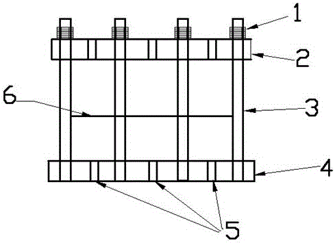
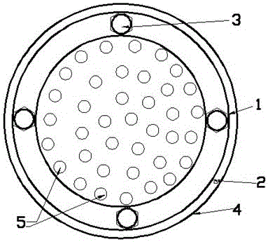
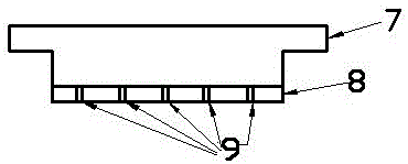
[0030] (1) Set up a device for dry-wet cycle and direct shear test under the condition of simulating soil load, which is composed of dry-wet cycle device and shear box. The dry-wet cycle device includes nut 1, fixed ring 2, vertical rod 3 , lower bottom plate 4, lower bottom plate drainage hole 5, ring knife 6, ring knife buckle 13, cross edge 7, upper cover plate 8 and upper cover plate drainage hole 9; ring knife 6 is divided into upper and lower halves on average, and the lower half The bottom is threaded, and the upper and lower halves of the ring cutter 6 can be fixed as a whole with the ring cutter buckle 13; The bottom thread is screwed together; the vertical rod 3 is fixedly connected with the lower base plate 4 and the entire length of the vertical rod 3 is threaded; the upper cover plate 8 is provided with a cross rib 7 and an upper cover drain hole, and the upper end of the cross rib is larger than the fixed ring 2. The outer diameter is 1 cm larger; the diameter of...


PUM


Abstract

The present invention discloses a method for conducting the dry-wet cycle and the direct shear test on the simulated load-bearing soil. A device composed of a dry-wet cycle device and a shear box is arranged. The dry-wet cycle device comprises a nut, a fixed ring, upright rods, a lower bottom plate, a lower bottom plate drain hole, a cutting ring, a cutting ring buckle, a cross rib, an upper cover plate, an upper cover plate drain hole, an upper shear box, a lower shear box and a shear box base. The upright rods are provided with threads along the whole length thereof and are fixedly connected with the lower bottom plate. The upper end of the cross rib on the upper cover plate is larger than the outer diameter of the fixed ring by 1 cm. The diameter of the upper cover plate is slightly smaller than the inner diameter of the cutting ring. The straight-line distance between diagonally arranged upright rods is slightly greater than the diameter of the experiment cutting ring. The shear box is composed of the base, the lower shear box and the upper shear box. The cycle device can be installed directly into the shear box. Through adjusting a direct shear apparatus and a dial indicator, the direct shear test can be conducted. Based on the method, the unloading condition is avoided during the entire process, from the sample preparation, the dry-wet cycle to the shear failure. Meanwhile, the water content change of the test can be accurately controlled.

Description

technical field [0001] The invention belongs to the technical field of geotechnical engineering test and engineering application, in particular to a method for performing dry-wet cycle and direct shear test under simulated soil load. Background technique [0002] The dry-wet cycle has a significant impact on the strength, modulus and other properties of the soil, and the dry-wet cycle of the soil is also one of the widely concerned issues in geotechnical engineering. At present, the research on the dry-wet cycle process of soil is mainly carried out through large-volume model experiments and laboratory small-volume sample experiments. However, the soil force simulated by the current experimental device is quite different from the actual engineering, and there are mainly the following limitations: (1) The dry-wet cycle process of the sample is carried out in the shear box of the direct shear instrument, and the moisture content is measured by the shear box. The measurement o...

Claims


Application Information

Patent Timeline
Patent Type & Authority Applications(China)
IPC IPC(8): G01N3/24
CPCG01N3/24G01N2203/0236
Inventor 吕海波董均贵吴畏谷建晓梁靖徐云山季春生蒋熠成果灯王勇
Owner GUILIN UNIVERSITY OF TECHNOLOGY
Why Eureka
Try Eureka