
Gas generator

A technology for gas generators and firearms, which is applied to gas generating devices, chemical instruments and methods, and vehicle safety arrangements, and can solve problems such as inability to maintain pressure resistance

Active Publication Date: 2016-08-17
DAICEL CORP
View PDF9 Cites 6 Cited by
  • Summary
  • Abstract
  • Description
  • Claims
  • Application Information

AI Technical Summary

Problems solved by technology

[0010] Although in paragraph 0011 of JP-A No. 2011-143777, it is described that a high-strength member such as a high-strength steel plate as a casing material of a gas generator is press-formed to form a small-diameter casing In particular, it becomes difficult to make the casing have sufficient strength in a low-temperature environment. In order to solve this problem, it is necessary to perform annealing and other treatments. However, when such annealing treatment is performed, the above-mentioned durable Pressure resistance against rise in internal pressure of the actuation gas generation chamber

Method used


Image

  • Gas generator
  • Gas generator
  • Gas generator

Examples


specific Embodiment approach

[0065] The present invention can be applied as long as the cup member and the igniter collar of the igniter can be assembled by press fitting.

[0066] For example, the present invention can be applied to: with JP-A No.2010-892 figure 1 The gas generator showing the combination of the first cup member 32 and the first igniter collar 22, the second cup member 41 and the second igniter collar 26 has JP-A No. 2010-70073 figure 1 The combination of the combustion chamber cup 30 and the collar 41 shown, the combination of the cup 132 and the collar 122 of FIG. 3 of JP-A No. 2007-118788, the combination of the cup 141 and the collar 126 are gas generators, and the like.

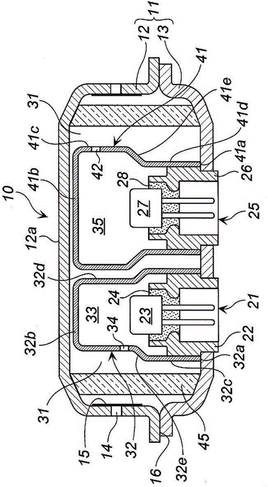
[0067] Use the following figure 1 (and of JP-A No.2010-892 figure 1 same) for explanation.

[0068] For the gas generator 10 , an outer casing is formed by a case 11 in which a diffuser case 12 and a closure case 13 are welded at joint portions 16 .

[0069] A plurality of gas discharge ports 14 are provided on...

Embodiment 1 and comparative example 1

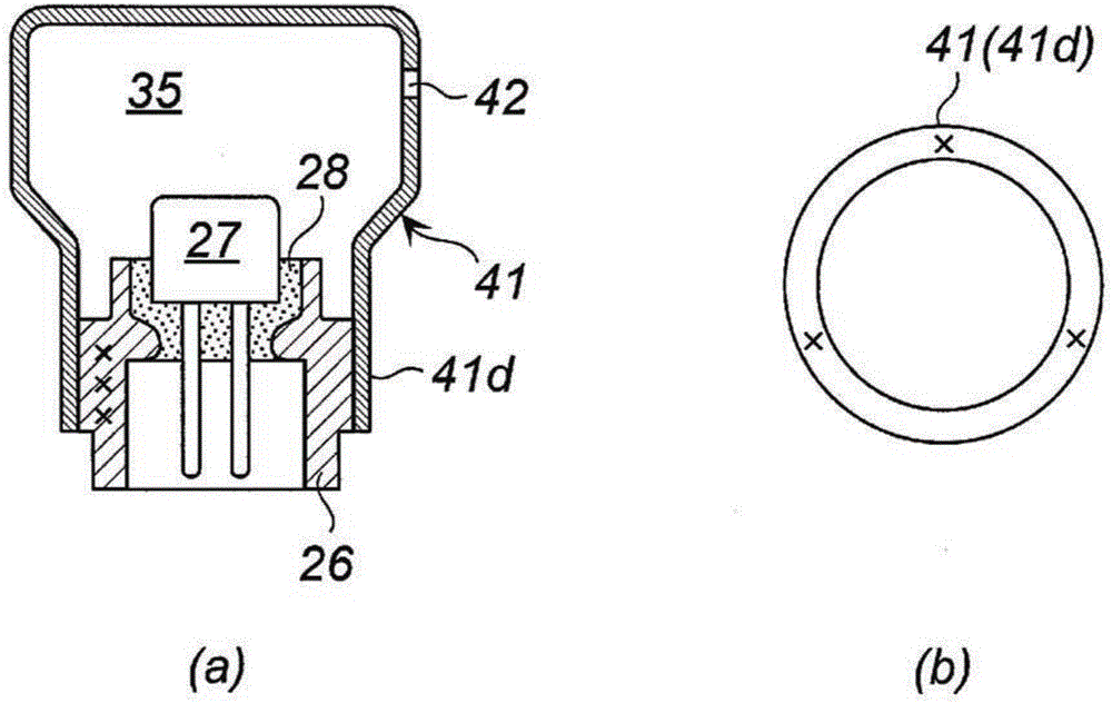
[0107] The method of measuring the average Vickers hardness of the first igniter collar 22 and the second igniter collar 26 is as follows. In addition, these measurement methods and measurement values ​​are the same, and are demonstrated below as the measurement method of the 2nd igniter collar 26.

[0108] Both the first igniter collar 22 and the second igniter collar 26 were formed of carbon steel (C content: 0.15% by mass), and both Example 1 and Comparative Example 1 were not annealed.


PUM


Abstract

The purpose of the present invention is to provide a gas generator that has a combination of an igniter collar for an igniter and a cup member as components such that the adhesion strength when the cup member is press-fitted to the igniter collar of the igniter can be made higher. This gas generator (10) has, inside a housing (11), igniters (23, 27) formed from igniter bodies surrounded by igniter collars (22, 26) and ignition means chambers (33, 35) which store an ignition charge, said gas generator (10) being characterized in that the ignition means chambers (33, 35) are formed by means of press-fitting such that opening-side inner circumferential wall surfaces of the ignition means chamber cups (32, 41) storing the ignition charge are brought into close contact with the outer circumferential wall surfaces of the igniter collars (22, 26) of the igniters (23, 27), and the ratio (Vh2 / Vh1) of the average Vickers hardness (Vh2) of the ignition means chamber cups (32, 41) to the average Vickers hardness (Vh1) of the igniter collars (22, 26) is in the range of 0.25-0.65.

Description

technical field [0001] The present invention relates to a gas generator that can be used in an airbag device of an automobile or the like. Background technique [0002] In a gas generator equipped with a gas generating agent used in an automobile airbag device or the like, an electric igniter for igniting the gas generating agent is accommodated in a housing. [0003] In an electric igniter, the igniter main body having a firing portion and a conductive pin is usually surrounded by an igniter collar, and the igniter collar portion is fixed to the case. [0004] The electric igniter located in the casing is often used in combination with a booster (or a gas generating agent that functions as a booster) in order to improve the ignition function of the gas generant. [0005] In the gas generator of JP-A No.H05-4035, the ignition chamber cover 3 is attached to the ignition housing 2 by screwing the screw portion 3a of the ignition chamber cover 3 and the nut 2c at the lower par...

Claims


Application Information

Patent Timeline
Patent Type & Authority Applications(China)
IPC IPC(8): B60R21/264B01J7/00
CPCB60R21/264B60R2021/26029B60R2021/26076B60R2021/2642
Inventor 奥山丘词
Owner DAICEL CORP
Learn More