
Plastic extruder

A technology for plastic extruders and outlets, which is applied in the field of plastic extruders and can solve problems such as unsustainable discharge

Inactive Publication Date: 2016-08-24
罗少堂
View PDF4 Cites 1 Cited by
  • Summary
  • Abstract
  • Description
  • Claims
  • Application Information

AI Technical Summary

Problems solved by technology

[0005] The purpose of the present invention is to provide a plastic extruder to solve the problem that the plastic extruder in the prior art cannot achieve continuous discharge

Method used


Image

  • Plastic extruder
  • Plastic extruder

Examples


Embodiment Construction

[0026] In order to enable those skilled in the art to better understand the technical solutions of the present invention, the present invention will be further described in detail below in conjunction with the accompanying drawings.

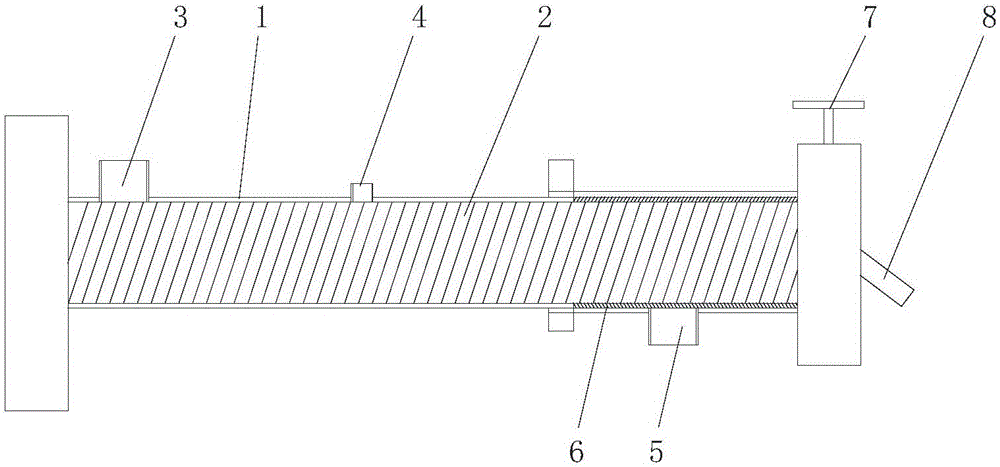
[0027] Such as figure 2 As shown, a plastic extruder provided by the embodiment of the present invention includes a barrel 1 and a screw 2 built in the barrel 1, an extrusion channel is formed between the outer wall of the screw 2 and the inner wall of the barrel 1, and the barrel 1 is provided with a feed port 3, an exhaust port 4, a discharge port and a sewage discharge port 8 in sequence along the extrusion channel, and also includes a filter 6, which is connected to the joint between the discharge port and the extrusion channel.

[0028] Specifically, other structures of the feed port 3, the screw 2, and the plastic extruder, such as the drive mechanism, transmission structure, etc., can refer to related prior art. The main improvement of th...


PUM


Abstract

The invention discloses a plastic extruder which comprises a cylinder and a screw rod arranged in the cylinder. An extruding channel is formed between the outer wall of the screw rod and the inner wall of the cylinder. A feeding port, an exhaust port, a discharging port and a dirt discharging opening are sequentially formed in the cylinder along the extruding channel. The plastic extruder further comprises a filtering part. The filtering part is connected to the connecting position of the discharging port and the extruding channel. By means of the plastic extruder, in the flowing direction of the extruding channel, the discharging port is located in the upstream part of the dirt discharging opening, impurities and plastic particles which are not melted are filtered out of the discharging port through a filtering part, due to the fact that the dirt discharging opening is located in the downstream part of the discharging port, discharging cannot be affected by dirt discharging, and the discharging port can achieve continuous discharging.

Description

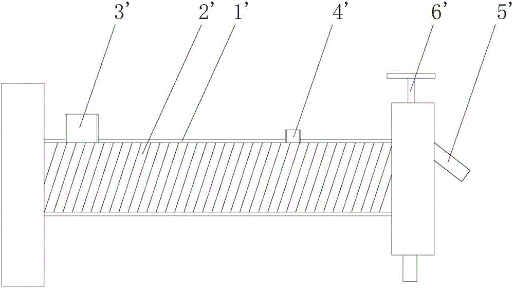
technical field [0001] The invention relates to plastic processing machinery, in particular to a plastic extruder. Background technique [0002] In plastic processing, the plastic extruder is usually called the main machine, because many methods of plastic processing, such as pipes, films, holding materials, monofilaments, extrusion nets, granulation, etc., are preceded by plastic extrusion. step. [0003] figure 1 It is a structural schematic diagram of a plastic extruder in the prior art, such as figure 1 As shown, the plastic extruder includes a barrel and a screw built in the barrel, an extrusion channel is formed between the outer wall of the screw and the inner wall of the barrel, and the extrusion channel is formed along the barrel on the barrel. The pressure channel is sequentially provided with a feed port, an exhaust port and a discharge port. When working, the material enters the extrusion channel through the feed port, the gas in the material overflows from th...

Claims


Application Information

Patent Timeline
IPC IPC(8): B29C47/38B29C47/66B29C47/68B29C47/08B29C48/395
CPCB29C48/025B29C48/397B29C48/681B29C48/69
Inventor 罗少堂
Owner 罗少堂
Learn More