
Double diaphragm steady flow anti-drip valve

An anti-drip valve and steady flow technology, which is applied in the direction of diaphragm valve, diaphragm, safety valve, etc., can solve the problems that the steady flow and anti-drip can not be realized at the same time, the fog cannot be formed, the flow is uneven, etc., and the structural design is novel, The effect of low cost and long service life

Active Publication Date: 2018-06-12
NANJING AGRI MECHANIZATION INST MIN OF AGRI
View PDF2 Cites 0 Cited by
  • Summary
  • Abstract
  • Description
  • Claims
  • Application Information

AI Technical Summary

Problems solved by technology

"Although this kind of anti-drip valve can realize the function of constant pressure and anti-drip, the structure is relatively complicated, especially the use of springs as elastic elements, the cost is high, and it cannot be used in large areas on micro-sprinklers in agricultural irrigation.
[0010] To sum up, the existing micro-sprinklers have the problems of not being able to form mist at low pressure and uneven flow when the working pressure is inconsistent. However, the products currently used for steady flow and anti-drip of micro-irrigation micro-sprinklers mainly have complex structures and low cost. High, unable to achieve steady flow and anti-drip functions at the same time

Method used


Image

  • Double diaphragm steady flow anti-drip valve
  • Double diaphragm steady flow anti-drip valve
  • Double diaphragm steady flow anti-drip valve

Examples


Embodiment Construction

[0043] In order to clarify the technical scheme and technical purpose of the present invention, the present invention will be further introduced below in conjunction with the accompanying drawings and specific embodiments.

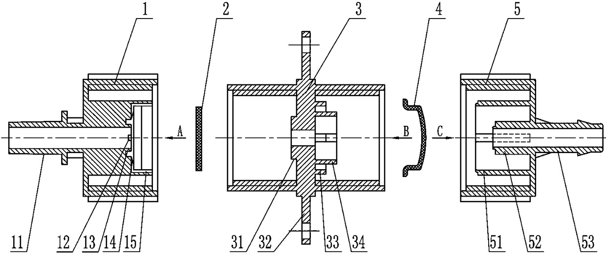
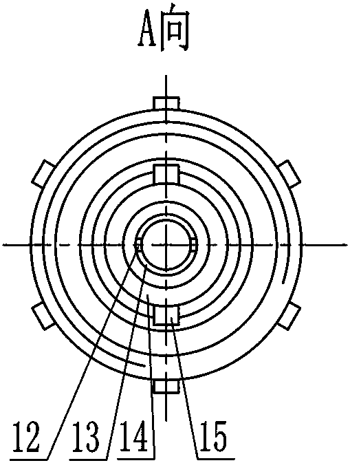
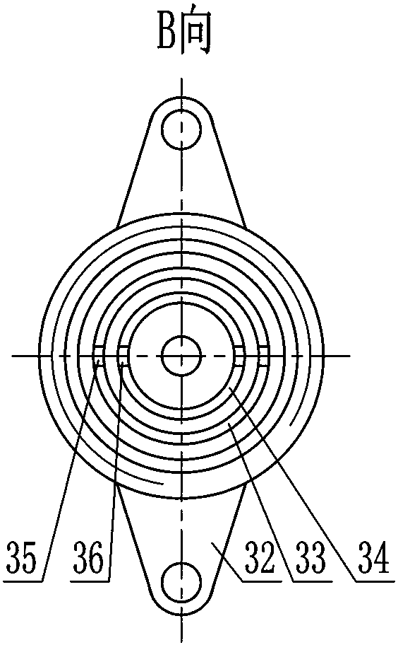
[0044] Such as Figure 1 to Figure 5 The shown double-diaphragm steady-flow anti-drip valve includes a steady-flow casing 1 , a steady-flow diaphragm 2 , an intermediate casing 3 , an anti-drip diaphragm 4 , and an anti-drip casing 5 .

[0045] One end of the steady flow casing 1 is connected to the micro-spray head 7 through a water outlet joint 11 , and the other end is connected to the left side of the middle casing 3 . The outer surface of the water outlet joint 11 has a taper of 1.2:100, and is closely matched with the micro-spray head 7 through the taper.

[0046] One end of the drip-proof housing 5 is connected to the water delivery pipe through an oblique water inlet joint 53 , and the other end is connected to the right side of the middle housing...


PUM


Abstract

The invention discloses a double-diaphragm flow-stabilizing and anti-dripping valve and provides a valve body structure design integrating a flow-stabilizing diaphragm and an anti-dripping diaphragm. Effects that the flow is adjusted to be stable during pressure change and a valve body is opened under the relatively high pressure to guarantee atomization and avoidance of water dripping can be realized simultaneously, besides, the valve is novel in structure design, easy to produce, convenient to assemble, low in cost and long in service life, various flow specifications can be designed, and the valve is applicable to various spray heads, has the higher economic value and social value and is particularly suitable for popularization and use in micro-spraying irrigation systems.

Description

technical field [0001] The invention relates to the technical field of micro-water irrigation, in particular to a steady-flow anti-drip valve device matched with a micro-sprinkler. Background technique [0002] In recent years, because micro-irrigation has many advantages such as water saving, high irrigation uniformity, labor saving, fertilizer saving, and production increase, it has developed rapidly and has been widely used. It has become an important technical means in agricultural production. At present, the national micro-irrigation application area It has reached more than 30 million mu. [0003] Micro-irrigation mainly includes two forms of drip irrigation and micro-sprinkler irrigation. Micro-sprinkler irrigation is a form of irrigation that uses refracting or rotating micro-sprinklers to spray low-pressure water or chemicals with micro-flow and low pressure on branches and leaves or on the ground through a pipeline system. The working pressure of micro-sprinkler ...

Claims


Application Information

Patent Timeline
Patent Type & Authority Patents(China)
IPC IPC(8): F16K17/02F16K7/12A01M7/00
CPCA01M7/005A01M7/0089F16K7/12F16K17/02
Inventor 金永奎薛新宇张玲周立新丁素明张宋超秦维彩周良富孔伟孙竹顾伟蔡晨崔龙飞王宝坤陈晨
Owner NANJING AGRI MECHANIZATION INST MIN OF AGRI
Learn More