Antenna device and mobile terminal

An antenna device and mobile terminal technology, applied to antennas, devices that allow antennas to work in different bands at the same time, antenna equipment with additional functions, etc., can solve the problems of increasing the thickness of mobile phones and the inability to realize all-metal casings, etc., to achieve Guaranteed overall effect

Active Publication Date: 2017-09-29
GUANGDONG OPPO MOBILE TELECOMM CORP LTD
View PDF7 Cites 0 Cited by
  • Summary
  • Abstract
  • Description
  • Claims
  • Application Information

AI Technical Summary

Problems solved by technology

[0003] The existing mobile phone antenna is installed on the mobile phone to receive and transmit mobile phone signals. Most of the existing mobile phone antennas are installed inside the mobile phone, that is, the built-in antenna design. The built-in antenna will increase the thickness of the mobile phone and cannot achieve an all-metal shell

Method used


Image

  • Antenna device and mobile terminal
  • Antenna device and mobile terminal
  • Antenna device and mobile terminal

Examples


Embodiment 1

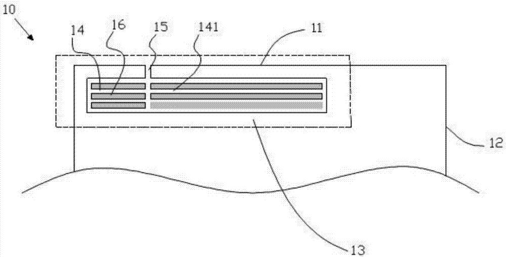
[0027] refer to figure 1 , shows the housing 10 according to the first embodiment of the present invention, the housing 10 is preferably an all-metal housing, which includes connected short sides 11 and long sides 12, the housing 10 includes a conductive region 13, the conductive Area 13 is in figure 1 Circled by a dotted line in , the conductive region 13 is provided with a micro-slit strip 14 and a slit 15 , and the micro-slit strip 14 is formed by a plurality of micro-slits 141 . exist figure 1 Among them, the micro-slits 141 are parallel to the short side 11 , the slit 15 is parallel to the long side 12 and perpendicularly intersects with a plurality of micro-slits 141 , and the opening of the slit 15 is located on the short side 11 . Preferably, the width of the micro-slits 141 is 0.009 to 0.5mm, which is not easy to attract the attention of consumers in appearance, and can ensure the integrity of the metal shell. A metal strip 16 is formed between adjacent micro-slits ...

Embodiment 2

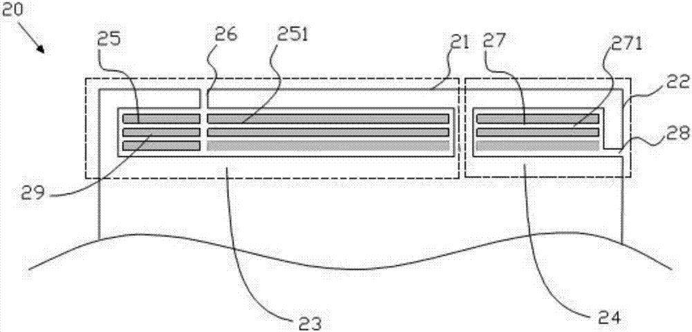
[0030] refer to figure 2 , shows a housing 20 according to a second embodiment of the present invention, the housing 20 is preferably an all-metal housing, which includes connected short sides 21 and long sides 22, the housing 20 includes a first conductive region 23 and The second conductive region 24, the first conductive region 23 and the second conductive region 24 are in figure 2 All are circled with a dotted line frame, the first conductive region 23 is provided with a first micro-slit strip 25 and a first slit 26, the second conductive region 24 is provided with a second micro-slit strip 27 and a second slit 28, and the first micro-slit The belt 25 is formed by a plurality of first micro-slits 251 , and the second micro-slit belt 27 is formed by a plurality of second micro-slits 271 . exist figure 2 Among them, the first micro-slit 251 and the second micro-slit 271 are parallel to the short side 21, the first slit 26 is parallel to the long side 22 and perpendicula...


PUM


Abstract

The invention provides an antenna device for a mobile terminal. The antenna device comprises first radio-frequency receiving and transmitting circuit, a first matching circuit, a second radio-frequency receiving and transmitting circuit, a second matching circuit and a shell, wherein the shell comprises a first conducting region; the first conducting region is provided with a first micro-gap strip and a first gap; the first micro-gap strip comprises a plurality of first micro-gaps; the first micro-gap is intersected with the plurality of first micro-gaps; the first radio-frequency receiving and transmitting circuit is electrically connected with the first conducting region through the first matching circuit; and the second radio-frequency receiving and transmitting circuit is electrically connected with the first conducting region through the second matching circuit. According to the antenna device provided by the invention, the overall appearance effect of the mobile terminal can be ensured; and meanwhile, receiving and transmitting of a high-frequency signal and a low-frequency signal can be achieved. The invention further provides the mobile terminal.

Description

technical field [0001] The invention relates to mobile communication technology, in particular to an antenna device and a mobile terminal. Background technique [0002] An antenna is a converter that converts the guided wave propagating on the transmission line into an electromagnetic wave propagating in an unbounded medium, usually free space, or vice versa. It is a component used in radio equipment to transmit or receive electromagnetic waves. Generally, antennas are reversible, that is, the same antenna can be used as both a transmitting antenna and a receiving antenna. The basic characteristic parameters of the same antenna as transmitting or receiving are the same. [0003] The existing mobile phone antenna is installed on the mobile phone to receive and transmit mobile phone signals. Most of the existing mobile phone antennas are installed inside the mobile phone, that is, the built-in antenna design. The built-in antenna will increase the thickness of the mobile phon...

Claims


Application Information

Patent Timeline
Patent Type & Authority Patents(China)
IPC IPC(8): H01Q5/20H01Q5/335H01Q5/50H01Q1/44H01Q1/36
CPCH01Q1/36H01Q1/44H01Q5/20H01Q5/335H01Q5/50
Inventor 王新宝赵宁
Owner GUANGDONG OPPO MOBILE TELECOMM CORP LTD
Why Eureka
Try Eureka