Electric connector

An electrical connector and docking part technology, applied in the field of reversible pluggable electrical connectors, can solve the problems of reduced strength of inserted components, many assembly parts, reduced product reliability, etc., to avoid mutual influence and facilitate injection molding. Effect

Active Publication Date: 2016-08-24
ALL BEST ELECTRONICS TECH CO LTD
View PDF6 Cites 13 Cited by
  • Summary
  • Abstract
  • Description
  • Claims
  • Application Information

AI Technical Summary

Problems solved by technology

[0004] In the existing USB Type-C socket connector, the insertion component is composed of an upper insertion component, a middle insertion component and a lower insertion component, wherein the upper insertion component is provided with an upper row of conductive terminals, the middle insertion component is provided with a central shielding piece, and the lower The plug-in component is equipped with a lower row of conductive terminals, thus forming a three-layer structure of the upper row of conductive terminals, the central shield and the lower row of conductive terminals. Cause tolerance accumulation, poor structural stability, and reduce product reliability

Method used


Image

  • Electric connector
  • Electric connector
  • Electric connector

Examples


Embodiment Construction

[0027] The present invention will be described in detail below in conjunction with various embodiments shown in the drawings. However, these embodiments do not limit the present invention, and any structural, method, or functional changes made by those skilled in the art according to these embodiments are included in the protection scope of the present invention.

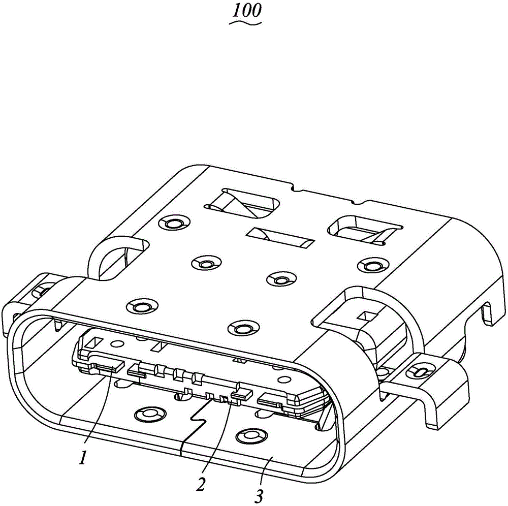
[0028] Please refer to Figure 1 to Figure 9 As shown, it is a preferred embodiment of the electrical connector 100 of the present invention. The electrical connector 100 includes a plurality of conductive terminals 1, an insulating body 2 injection-molded on the periphery of the conductive terminals 1, and an insulating body 2 coated on the insulating body 2. Outer shell 3.

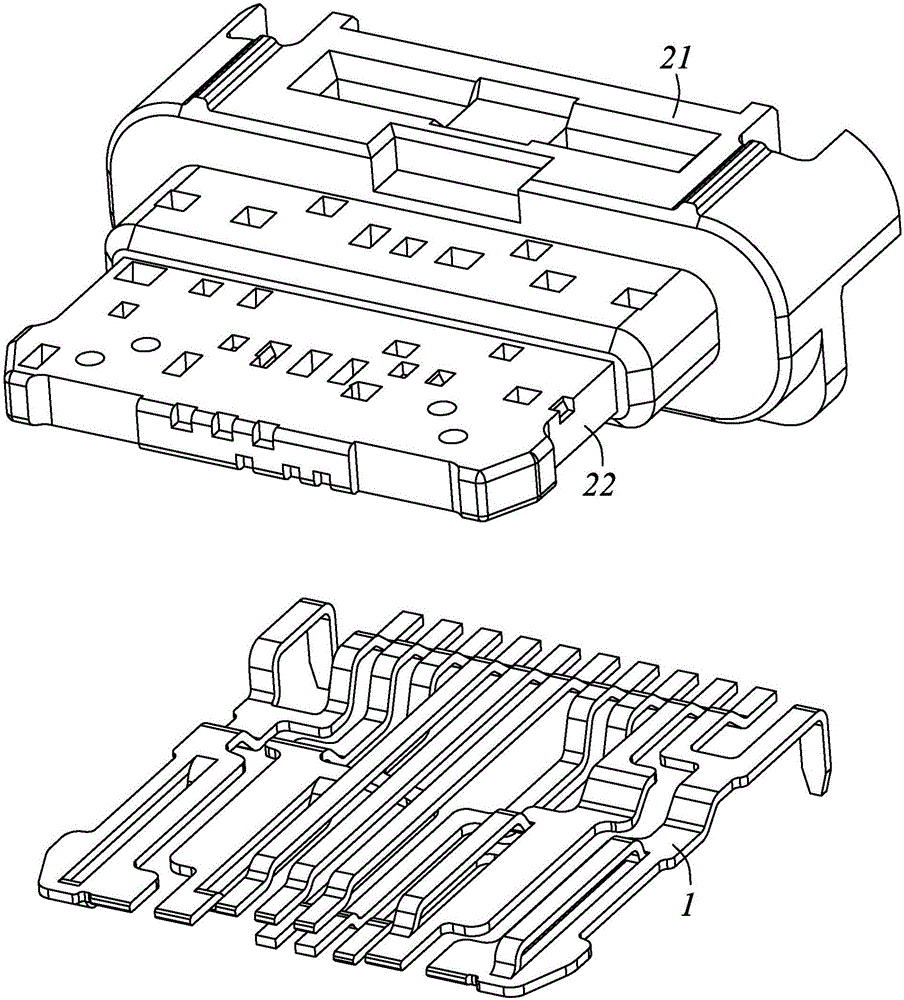
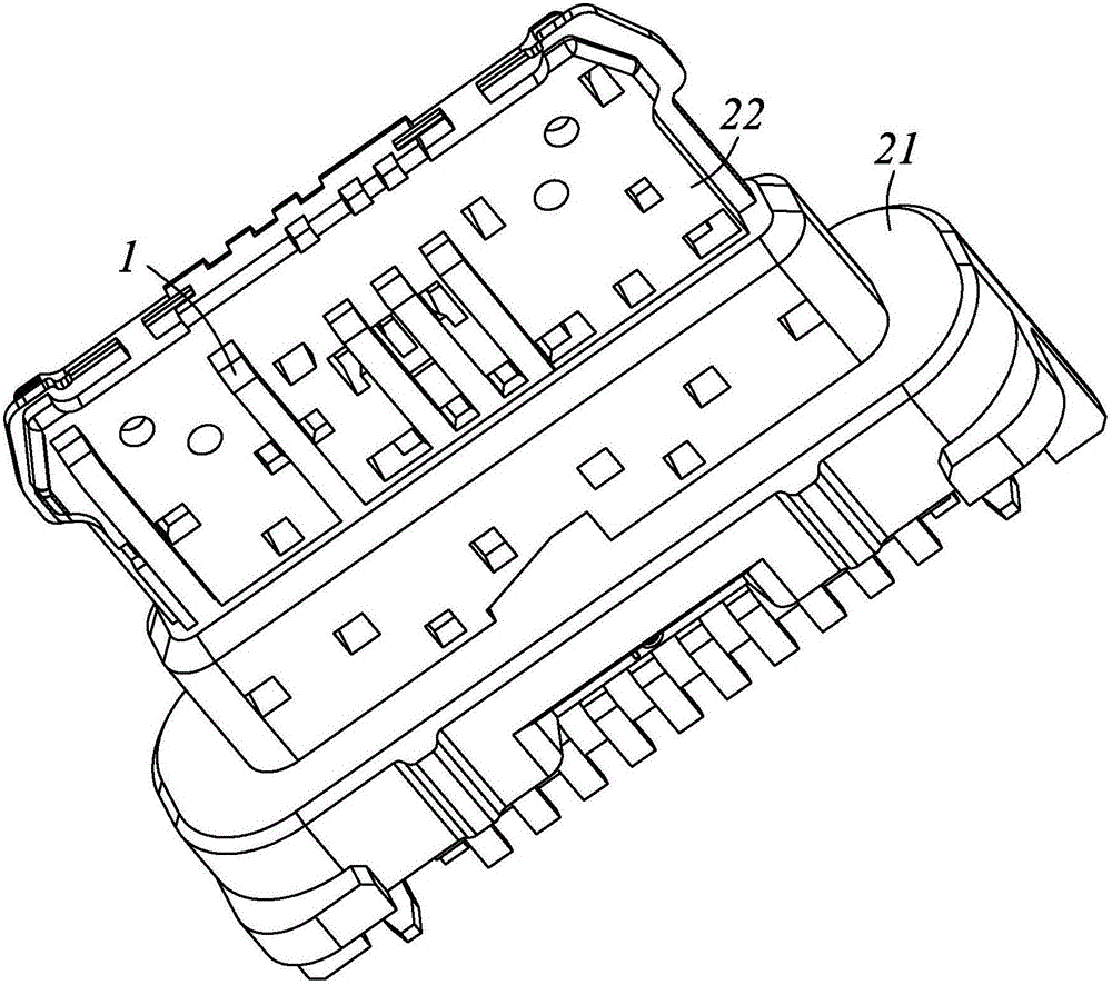
[0029] Please Figure 1 to Figure 3 As shown, the insulating body 2 is integrally formed, and has a base 21 and a tongue 22 extending forward from the base.

[0030] Please refer to Figure 4 to Figure 9 As shown, the conductive terminal 1...


PUM


Abstract

The invention provides an electric connector. The electric connector comprises multiple conductive terminals and an insulating body which is arranged on the peripheries of the conductive terminals in an injection molding manner; the insulating body is provided with a forwardly-extended tongue-shaped plate; each conductive terminal is provided with a main body part which is embedded and fixed in the insulating body, butted parts which are exposed to the surface of the tongue-shaped plate and welding pins which extend out of the insulating body; the two rows of the butted parts are arranged on the upper side and the lower side of the tongue-shaped plate respectively; the conductive terminals which are corresponding to the two rows of the butted parts respectively are the same in the signal transmission type and are arranged along opposite directions; and the main body parts and the welding pins of the multiple conductive terminals are arranged in a staggered manner in the transverse direction of the insulating body. According to the electric connector provided by the invention, mutual influence in the injection molding process of the insulating body can be avoided; the electric connector can be formed in one time in the injection molding manner conveniently; and in addition, the conductive terminals can perform the functions of metal shielding sheets as well.

Description

technical field [0001] The invention relates to the technical field of connectors, in particular to a reversible plug-in electrical connector. Background technique [0002] With the rapid development of science and technology in the electronics industry, the volume of electronic products is developing along the trend of becoming thinner and shorter, which requires the components of electronic products to be smaller and smaller, and the connector industry is the first to bear the brunt . [0003] Due to the requirement for a smaller size of the new generation of USB Type-C connectors, this leads to better mechanical performance requirements and more difficult product design. In order to face thinner and thinner equipment and ensure the reliability of product structure, major manufacturers have launched corresponding structural designs. [0004] In the existing USB Type-C socket connector, the insertion component is composed of an upper insertion component, a middle insertio...

Claims


Application Information

Patent Timeline
Patent Type & Authority Applications(China)
IPC IPC(8): H01R13/02H01R13/648H01R13/405
CPCH01R13/02H01R13/405H01R13/648H01R13/658
Inventor 彭易平翟重阳张安定程正云
Owner ALL BEST ELECTRONICS TECH CO LTD
Why Eureka
Try Eureka