Guide plate type punching die

A guide plate type punching die and guide plate technology, applied in the field of punching die, can solve the problems of limited pressure of the pressing plate, difficulty in processing small holes, breakage of punches in assembly size, etc., and achieve good guiding conditions and are conducive to punching. Cutting, pressure and reliable effect

Active Publication Date: 2016-08-31
JINGDE WANXING ELECTRONICS & ELECTRICAL APPLIANCES FACTORY
View PDF5 Cites 2 Cited by
  • Summary
  • Abstract
  • Description
  • Claims
  • Application Information

AI Technical Summary

Problems solved by technology

[0002] The punching die is a common equipment in the stamping process of parts. It mainly includes a punch and a die. The shape of the punch can be selected according to the hole type. The most common one is a circular punch, which is a round In order to ensure the stable and reliable installation of the punch, the punch generally has a slender connecting section and a guide section, which leads to the weak structural strength of the punch itself, and a slight error in the assembly size can easily cause the punch to break, especially When processing thicker plates, smaller punches cannot complete the punching task at all, so it is very difficult to process small holes on thicker plates; in addition, in terms of workpiece positioning, although the existing punching die has a pressing plate structure, but the pressure of the binder plate is limited. In the high-load punching task, it is difficult to ensure that the workpiece does not move. Therefore, the existing punching die is still difficult to meet the needs of industrial production.

Method used


Image

  • Guide plate type punching die

Examples


Embodiment Construction

[0014] The following examples are a further description of the content of the present invention as an explanation of the technical content of the present invention, but the essential content of the present invention is not limited to the following examples, those of ordinary skill in the art can and should know any Simple changes or replacements of the essential spirit of the invention shall fall within the scope of protection required by the present invention.

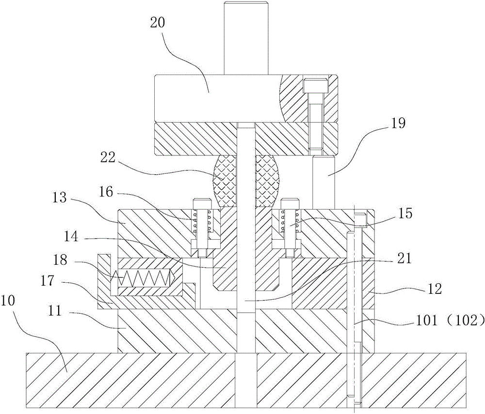
[0015] Such as figure 1 As shown, a guide plate type punching die includes a fixed lower die base 10 and an upper die base 20 reciprocating up and down. The upper die base 20 is provided with a punch 21, and the lower die base 10 is A die 11 is provided, a side guide plate 12 is provided above the die 11, a cavity for accommodating workpieces to be processed is provided in the middle of the side guide plate 12, a fixed plate 13 is provided above the side guide plate 12, and a through hole is provided in the middle of ...


PUM


Abstract

The invention belongs to the technical field of punching dies and particularly relates to a guide plate type punching die. The guide plate type punching die comprises a lower die base arranged fixedly and an upper die base arranged in an up-down reciprocating mode. The upper die base is provided with a punching head. The lower die base is provided with a female die body. A side guide plate is arranged above the female die body. A fixing plate is arranged above the side guide plate. A through hole is formed in the middle of the fixing plate and internally provided with a movable guide plate. The middle of the movable guide plate is provided with a hole channel. The punching head is slidably matched with the movable guide plate and further sleeved with a polyurethane rubber mat. When the upper die base descends, the polyurethane rubber mat extrudes the movable guide plate to enable the movable guide plate to make contact with a workpiece at first and press the workpiece, and then the upper die base continues to descend to fold the punching head with the female die body, so that the punching action is completed. Compared with a spring, the pressure provided by the polyurethane rubber mat is more reliable; and in addition, the punching head can have a very good guide condition through the movable guide plate, and a thick material can be punched through a small male die.

Description

technical field [0001] The invention belongs to the technical field of punching dies, in particular to a guide plate type punching die. Background technique [0002] The punching die is a common equipment in the stamping process of parts. It mainly includes a punch and a die. The shape of the punch can be selected according to the hole type. The most common one is a circular punch, which is a round In order to ensure the stable and reliable installation of the punch, the punch generally has a slender connecting section and a guide section, which leads to the weak structural strength of the punch itself, and a slight error in the assembly size can easily cause the punch to break, especially When processing thicker plates, smaller punches cannot complete the punching task at all, so it is very difficult to process small holes on thicker plates; in addition, in terms of workpiece positioning, although the existing punching die has a pressing plate structure, but the pressure o...

Claims


Application Information

Patent Timeline
Patent Type & Authority Applications(China)
IPC IPC(8): B21D28/34
CPCB21D28/34
Inventor 王英明
Owner JINGDE WANXING ELECTRONICS & ELECTRICAL APPLIANCES FACTORY
Why Eureka
Try Eureka