Heavy edge tearing knife rest convenient to adjust and working principle thereof

A tool holder and side knife technology, applied in metal processing and other directions, to achieve the effect of easy adjustment, easy installation, and loosening prevention

Pending Publication Date: 2022-02-25
广东天章信息纸品有限公司
View PDF0 Cites 0 Cited by
  • Summary
  • Abstract
  • Description
  • Claims
  • Application Information

AI Technical Summary

Problems solved by technology

[0004] The purpose of the present invention is to provide a conveniently adjustable heavy-duty edge tearing tool holder and its working principle to solve the technical problem of conveniently adjusting the position of the tool and cutting pressure during the production of printing paper

Method used


Image

  • Heavy edge tearing knife rest convenient to adjust and working principle thereof
  • Heavy edge tearing knife rest convenient to adjust and working principle thereof

Examples


Embodiment Construction

[0020] In order to make the implementation objectives, technical solutions and advantages of the present invention clearer, the solutions of the present invention will be described in detail below in conjunction with the accompanying drawings.

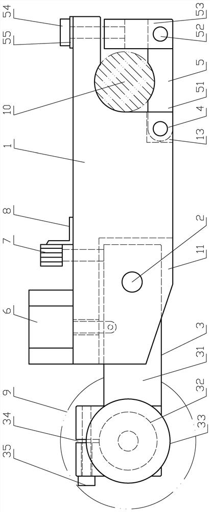
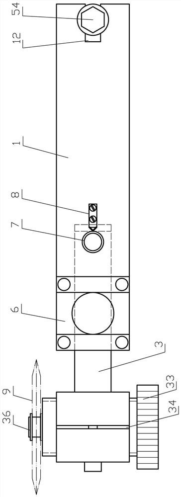
[0021] as attached figure 1 and figure 2 As shown, this conveniently adjustable heavy-duty tearing knife rest of the present invention includes a knife rest body 1, and a long fork 11 is arranged at the lower end of the head of the said knife rest body 1, and a straight pin I2 is hinged in the long fork 11. A tool holder head 3; the tail of the tool holder body 1 is in the shape of an inner arc at right angles, with a short fork opening 12 at the tail end and a right angle fork opening 13 at the lower end, and a cylindrical pin II 4 is used to hinge a shaft holding assembly in the right angle fork opening 13 5. The shaft holding assembly 5 includes a connecting block 51, one end of the connecting block 51 is hinged with the right ang...


PUM


Abstract

The invention relates to a heavy edge tearing knife rest convenient to adjust and a working principle thereof. The knife rest is characterized in that: a knife rest head is hinged to the head of a knife rest body, a journal sticking assembly is hinged to the tail of the knife rest body, an air cylinder is fixed to the upper end of the head, a piston rod of the air cylinder is hinged to the knife rest head, the air cylinder is connected to a compressed air system through an air pipe, the compressed air system further comprises an air pressure adjusting device, a limiting screw is further arranged at the upper end of the head of the tool rest body and abuts against the tail of the tool rest head, the limiting screw is prevented from loosening through an elastic pressing angle, the tail of a tool bit body of the tool rest head is hinged to the tool rest body, the head of the tool bit body is provided with a tool installing column through a threaded through hole, the upper end of the threaded through hole is provided with a notch and a locking screw, and an edge tearing knife is installed on the tool installing column. The edge tearing knife rest with the structure is very convenient, rapid and accurate in the aspects of rough positioning of the knife rest, accurate positioning of the edge tearing knife, gap adjustment of the edge tearing knife, cutting pressure adjustment and the like, and solves the technical problem that the position of the knife and the cutting pressure can be conveniently adjusted when printing paper is produced.

Description

technical field [0001] The invention relates to a printing paper processing equipment, in particular to a conveniently adjustable heavy-duty edge tearing tool holder and its working principle. Background technique [0002] Computer printing paper with conveying holes often needs to be cut out with a dotted line knife on the edge of the conveying hole, so that the customer can tear off the conveying holes on both sides after printing, especially for multi-column carbonless copy printing paper, after tearing off the conveying hole , the multi-links are naturally separated, and the layered distribution is convenient. This kind of edge tearing line is cut with a circular dotted line cutter in production and processing. The dotted line knife is installed on a tearing edge knife holder. Generally, each tearing edge line is processed with a knife, and the edge tearing knife holder is installed on a fixed circular installation shaft. . The cutting principle of this kind of cutter ...

Claims


Application Information

Patent Timeline
Patent Type & Authority Applications(China)
IPC IPC(8): B26D7/26
CPCB26D7/2621B26D7/2635
Inventor 叶尉东张世雄李云峰
Owner 广东天章信息纸品有限公司
Why Eureka
Try Eureka