Laminating machine

A film laminating machine and film laminating mechanism technology, applied in the direction of winding strips, sending objects, packaging, etc., can solve the problems of inaccurate film laminating position, low work efficiency, poor product quality, etc., achieve high speed, high efficiency, and overcome operation cumbersome effect

Active Publication Date: 2017-11-28
DONGGUAN LVKE PLASTIC & RUBBER PROD CO LTD
View PDF5 Cites 0 Cited by
  • Summary
  • Abstract
  • Description
  • Claims
  • Application Information

AI Technical Summary

Problems solved by technology

[0002] When attaching film around the surface of electronic products, due to the different lengths around the product, films of different lengths need to be attached around the product, and the film is generally attached to the film paper, and the film needs to be separated from the film paper during use. At the same time, it is necessary to correct the position and transport the product to the standard operating position for film application. After the film application, the surrounding film needs to be rolled flat. At this time, an electronic product film application machine is needed, and the existing technology is generally manual. Film, its work efficiency is low, the position of the film is not accurate, the labor intensity is high, and the product quality is poor

Method used


Image

  • Laminating machine
  • Laminating machine
  • Laminating machine

Examples


Embodiment Construction

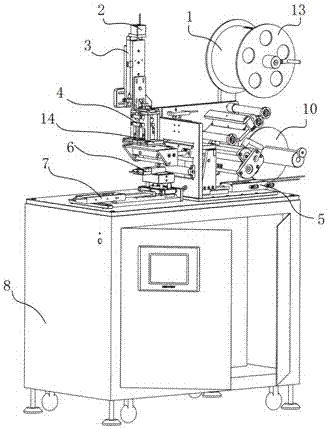
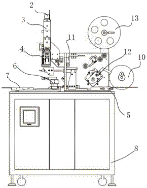
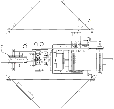
[0016] The present invention will be described in detail below in conjunction with the accompanying drawings and specific embodiments, where the schematic embodiments and descriptions of the present invention are used to explain the present invention, but not to limit the present invention.

[0017] refer to figure 1 , figure 2 , image 3 and Figure 5 , the object of the present invention is to provide a film laminating machine, including a chassis 8, the base is arranged on the chassis 8, two connected first support plates and second support plates at 90° are fixed on the base, and the base is set There are a base cylinder 7 and a film pulling cylinder 5, the base cylinder 7 is connected to the jig base 6, and the upper end of the base is also provided with a receiving assembly 10, a roll film assembly 12, a protective film fixing assembly 13 and a film assembly 4, the receiving assembly 10 Connect the film roll assembly 12 through a connecting rod. Above the film roll a...


PUM


Abstract

The invention aims to provide a laminator. The laminator comprises a case, wherein a base is arranged on the case; a first supporting plate and a second supporting plate which are connected with each other and form an included angle of 90 degrees are fixed on the base; a base cylinder and a film drawing cylinder are arranged on the base; the base cylinder is connected with a jig base; a collecting assembly, a film winding assembly, a protecting film fixing assembly and a laminating assembly are further arranged at the upper end of the base; a laminating mechanism is fixed on the second supporting plate; the jig base is arranged at the bottom of the laminating mechanism; the laminating mechanism comprises the laminating assembly, film absorbing plates, roller mechanisms and an elastic assembly, the two film absorbing plates are arranged below the laminating assembly, the elastic assembly is arranged between the two film absorbing plates, a spring is arranged above the elastic assembly, the roller mechanisms are arranged on two sides of the spring, and side brush silicone gel pieces are arranged between the film absorbing plates and the elastic assembly; a laminating cylinder is arranged at the laminating mechanism, is connected with the laminating assembly and drives the laminating assembly to move up and down; and an ejecting cylinder is arranged above the laminating cylinder.

Description

technical field [0001] The invention relates to a film sticking device, in particular to a film sticking machine. Background technique [0002] When attaching film around the surface of electronic products, due to the different lengths around the product, films of different lengths need to be attached around the product, and the film is generally attached to the film paper, and the film needs to be separated from the film paper during use. At the same time, it is necessary to correct the position and transport the product to the standard operating position for film application. After the film application, the surrounding film needs to be rolled flat. At this time, an electronic product film application machine is needed, and the existing technology is generally manual. Sticking film, its work efficiency is low, the position of sticking film is inaccurate, labor intensity is big, and product quality is poor. Contents of the invention [0003] The present invention is aimed...

Claims


Application Information

Patent Timeline
Patent Type & Authority Patents(China)
IPC IPC(8): B65B33/02B65H37/00B65H16/04
CPCB65B33/02B65H16/04B65H37/002B65H2701/19B65H2801/81
Inventor 纪万宝
Owner DONGGUAN LVKE PLASTIC & RUBBER PROD CO LTD
Why Eureka
Try Eureka