Automatic film laminating machine

A film laminating machine and automatic technology, applied in packaging, climate sustainability, final product manufacturing, etc., can solve the problems of manual film lamination difficulty and labor intensity increase, inaccurate film lamination position, low film lamination accuracy, etc., to simplify the film lamination process , good consistency, fast effect

Active Publication Date: 2022-06-03
江苏钜芯集成电路技术股份有限公司
View PDF0 Cites 0 Cited by
  • Summary
  • Abstract
  • Description
  • Claims
  • Application Information

AI Technical Summary

Problems solved by technology

At present, most manufacturers still use manual methods to attach protective labels to the lens surface of the photosensitive chip one by one. The work efficiency is low and the position of the film is not accurate. Labor intensity has also been greatly increased
In order to solve the problem of manual film sticking, some manufacturers also use special automatic film laminating machines to arrange and attach the protective labels on the release film to form a conveying film, and then wrap the conveying film on the conveying film roller. It is necessary to make each protective label Align the lens surface of each photosensitive chip separately, so that the protective label is attached to the lens surface of the photosensitive chip, which can improve work efficiency to a certain extent; but such an automatic film laminating machine is not only complicated in overall structure, high in cost, but also accurate in pasting the film. degree is not high

Method used


Image

  • Automatic film laminating machine
  • Automatic film laminating machine
  • Automatic film laminating machine

Examples


Embodiment Construction

[0029] The present invention will be further described below in conjunction with the specific drawings.

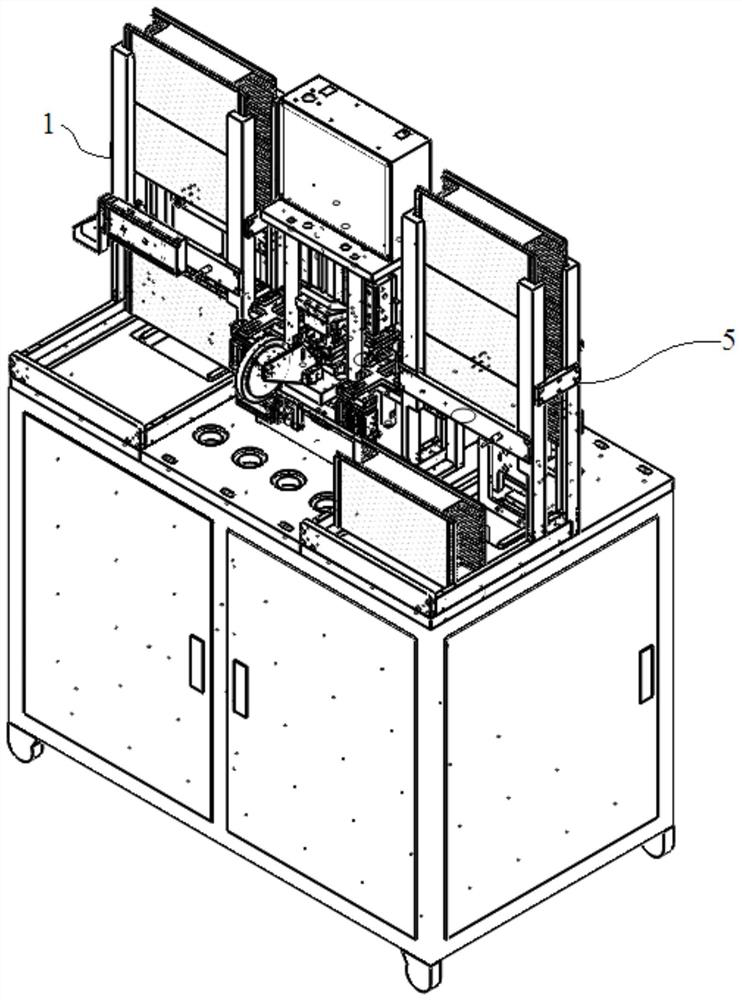
[0030] like figure 1 As shown, the automatic film laminating machine of the present invention includes a feeding component 1 , a material moving component 2 , a film pulling component 3 , a film pressing component 4 and a material receiving component 5 .

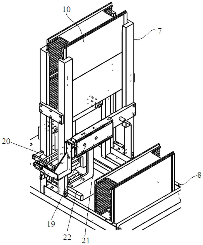
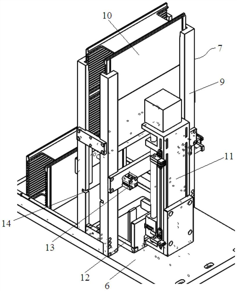
[0031] like figure 2 , image 3 As shown, the loading assembly includes a loading base plate 6 on which a loading area 7 and an empty material box area 8 are set. The loading area 7 is surrounded by four loading frames 9. The loading area 7 Containers 10 stacked in sequence from top to bottom are accommodated in the middle, and a lift 11 is installed on the side of the loading base plate 6 away from the empty container area 8. Located below the bottommost material box 10, a material pressing cylinder 13 is installed on one side of the charging area 7. When the extension rod of the material pressing cylinder 13 is ext...


PUM


Abstract

The invention relates to an automatic film laminating machine, which is characterized in that it includes a feeding assembly and a film pressing assembly, the feeding assembly includes a feeding bottom plate, a loading area is set on the feeding bottom plate, and a driving material box is installed on the feeding bottom plate The lifter, the inner wall of the material box is provided with a groove for placing the chip frame, and material transfer holes are provided on both sides of the chip frame; a discharge port is provided at one end of the charging area, and a pushing device is installed at the other end; The lamination area is equipped with a material transfer channel and a film pressing assembly, and a material transfer assembly is installed on one side of the material transfer channel. The material transfer assembly includes a sliding material transfer table that can move horizontally, and a material transfer claw that can be lifted can be installed on the sliding material transfer table; The film pressing assembly includes a film pressing cylinder, the protruding end of the film pressing cylinder is connected to a punch rod, the punch rod is sleeved in the upper pressing block, the lower pressing block is installed under the upper pressing block, and a circular knife edge is arranged on the lower pressing block; A film belt is passed between the pressing block and the lower pressing block. The film sticking machine of the invention can realize precise film sticking and has high working efficiency.

Description

technical field [0001] The invention relates to an automatic laminating machine, which belongs to the technical field of semiconductor chip packaging. Background technique [0002] Photosensitive chips such as CMOS Image Sensor (CIS) have been widely used in many fields. For example, an optical mouse used in computer operation, the optical mouse has a light-emitting diode inside, and the light emitted by the light-emitting diode illuminates the bottom surface of the optical mouse, and then part of the light reflected back from the bottom surface of the optical mouse passes through a set of optical lenses , transferred to the micro-imager for imaging. In this way, when the optical mouse moves, its movement track will be recorded as a set of coherent images captured at high speed. Finally, the digital microprocessor inside the optical mouse is used to analyze and process a series of images captured on the moving track. By analyzing the changes in the position of the feature ...

Claims


Application Information

Patent Timeline
Patent Type & Authority Patents(China)
IPC IPC(8): B65B33/02
CPCB65B33/02Y02P70/50
Inventor 谭礼祥姬起群
Owner 江苏钜芯集成电路技术股份有限公司
Why Eureka
Try Eureka