Grouting, pipe fixing and plugging technique for deep drainage hole wall in water inrush borehole

A technology of drainage holes and grouting, which is applied in earthwork drilling, sealing/packing, wellbore/well components, etc. It can solve the problems of grout gushing out and drilling holes that cannot be blocked, and achieve the effect of reducing water output

Inactive Publication Date: 2016-08-31
安徽恒源煤电股份有限公司
View PDF3 Cites 8 Cited by
  • Summary
  • Abstract
  • Description
  • Claims
  • Application Information

AI Technical Summary

Problems solved by technology

[0003] The purpose of the present invention is to provide a deep drainage hole wall grouting solid pipe plugging process in the water inrush borehole. This method realizes the control of the borehole plugging and the water outlet of the roadway floor around the borehole, and solves the problem of water in the hole. The sh

Method used


Image

  • Grouting, pipe fixing and plugging technique for deep drainage hole wall in water inrush borehole

Examples


Embodiment Construction

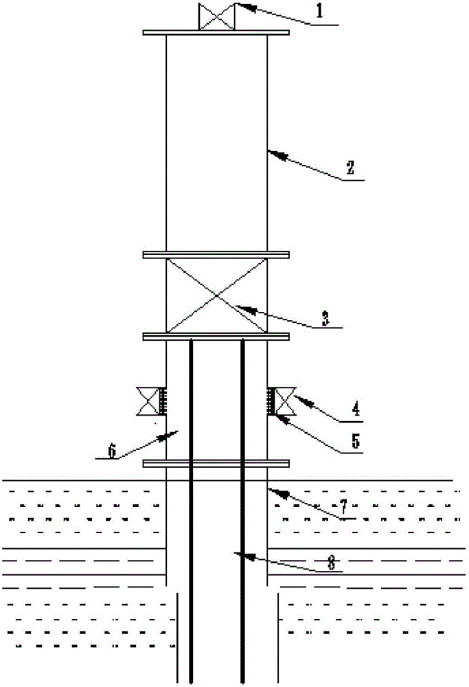
[0014] Referring to the attached drawing, the plugging process of the deep drainage hole wall grouting solid pipe in the water inrush drilling hole is used to drain and release the water from the deep aquifer in the hole by inserting a small-diameter drainage pipe 8 into the deep part of the orifice pipe 7 , using the original hole wall to inject grout into the hole, the specific process steps are as follows:

[0015] 1) Put the small diameter drainage tube 8 into the hole;

[0016] 2) Install the hole wall grouting device 6 at the orifice. The hole wall grouting device 6 includes the grouting gate valve 1, the material pipe 2, the hole wall gate valve 3, the pressure relief valve 5, the orifice pipe 7 and the material pipe 2 A pressure relief valve 5 is provided at the connection between them;

[0017] 3), the orifice is installed with a drainage orifice gate valve 4;

[0018] 4) Grouting through the hole wall grouting device 6 and the material pipe 2 into the hole through ...


PUM


Abstract

The invention discloses a grouting, pipe fixing and plugging technique for a deep drainage hole wall in a water inrush borehole. Drainage and pressure relief are conducted on water outlet of a deep water-bearing stratum in a hole by placing a small-diameter drainage pipe 8 into a deep portion of an orifice pipe 7. Grouting is conducted on the interior of the hole through the hole wall of an original hole. The technique specifically comprises the following steps that (1) the small-diameter drainage pipe 8 is placed in the hole; (2) a hole wall grouting device 6 is installed at the orifice, and the hole wall grouting device 6 comprises a grouting pulp inlet brake valve 1, a pulp pipe 2, a hole wall brake valve 3 and a pressure release valve 5; (3) a drainage orifice brake valve 4 is installed at the orifice; (4) pulp is injected into the hole through the hole wall by means of the hole wall grouting device 6 and the pulp pipe 2, and the pulp comprises aggregates and cement paste; and (5) after a water outlet crack channel of a roadway floor is blocked, the water-bearing stratum is subjected to grouting through the drainage orifice brake valve 4. By the adoption of the technique, the problem that a large amount of water in the hole gushes out from a shallow bottom slab of a surrounding roadway for pressure relief, when a conventional orifice direct grouting method is used, a large amount of pulp gushes out from water bursting points of the shallow bottom slab of the surrounding roadway, and consequentially the drill hole cannot be plugged is solved.

Description

technical field [0001] The invention relates to a borehole grouting plugging process, in particular to a grouting solid pipe plugging process in deep drainage hole walls in water inrush boreholes. Background technique [0002] The in-situ stress in the deep part of the mine is high, which often causes the underground hydrological drilling casing to break, and the high-flow and high-pressure water in the hole is connected to the shallow crack of the roadway through the broken casing, resulting in floor heaving and water inrush accidents in the roadway around the drilling hole. Such accidents must be dealt with in a timely manner to block the water outlet borehole. Since the water in the hole gushes out through the shallow floor of the surrounding roadway to relieve pressure, when the conventional orifice direct grouting method is used, a large amount of grout will flow from the shallow floor of the surrounding roadway. Gushes out, making the borehole unable to be plugged. C...

Claims


Application Information

Patent Timeline
IPC IPC(8): E21B33/13
CPCE21B33/13
Inventor 孙爱国秦磊
Owner 安徽恒源煤电股份有限公司
Why Eureka
Try Eureka