Upper part of a valve

A technology of bonnet and valve seat, applied in sliding valves, valve details, multi-way valves, etc., can solve problems affecting the durability of filter modules

Active Publication Date: 2016-08-31
FLUHS DREHTECHN
View PDF6 Cites 3 Cited by
  • Summary
  • Abstract
  • Description
  • Claims
  • Application Information

AI Technical Summary

Problems solved by technology

This affects the persistence of filter modules

Method used


Image

  • Upper part of a valve
  • Upper part of a valve
  • Upper part of a valve

Examples


Embodiment Construction

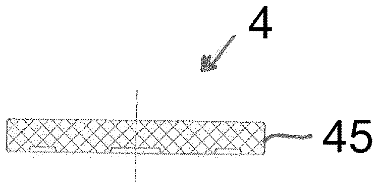
[0084] The bonnet chosen as embodiment consists essentially of a top piece 1 which is passed through by a mandrel 2 guided radially along it. The control disk 3 is positively connected to the spindle 2 and guided radially in the top part 1 . On the side of the control disk 3 facing away from the spindle 2 , a disk 4 is arranged in a rotationally fixed manner in the top part 1 , to which a bottom part 5 is connected. The bottom part 5 is provided with a lip seal 6 by means of which the bottom part 5 is sealed against the through disk 4 and against the valve seat 7 . The bottom part 5 thus "floats" axially between the valve seat 7 and the passage disc 4 .

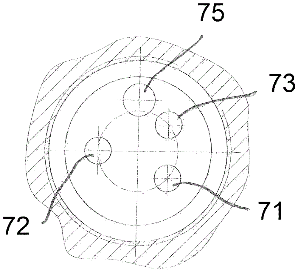
[0085] The top part 1 consists of a symmetrical hollow body which is open at both end faces. In the exemplary embodiment the top part 1 is made as a brass swivel part. On its side facing the bottom part 5 , the top part 1 has a sleeve-shaped part 10 in which two through windows 11 are arranged opposite each other. On the ...


PUM


Abstract

The invention relates to a valve upper part for sanitary fittings, comprising a head piece which accommodates a bottom part having two inlet channels and at least one first outlet channel, and a disc control with a control disc which is displaceable by means of a rotatably mounted spindle relative to a rotationally fixed transmission disc A connection channel (31) is introduced into the control disc (3), via which a first inlet channel (51) and the first outlet channel (52) can be connected in a rotational position of the control disc (3) relative to the transmission disc (4).

Description

technical field [0001] The invention relates to a valve cap for sanitary fittings having the features stated in the preamble of claim 1 . Background technique [0002] Valve caps are frequently used in sanitary fittings in which a disk controller (Scheibensteuerung) with a control disk (Steuerscheibe) and a passage disk (Durchlassscheibe) is arranged, which can be operated via a spindle (Spindel) so that the passage disk Rotate to control drainage. Such an exchangeable bonnet, as described for example in DE 20 2005 003 127 U1, can be used in fitting housings of different designs. The water taken from the fittings is fed into the filter module beforehand in increased volume, thereby improving its quality. In this case, the filter module is usually connected upstream of the valve cap, so that the filter module is continuously loaded with water pressure. This affects the persistence of the filter module. Contents of the invention [0003] Here, the present invention provi...

Claims


Application Information

Patent Timeline
Patent Type & Authority Applications(China)
IPC IPC(8): F16K27/08F16K27/04F16K3/314F16K11/074
CPCF16K3/314F16K11/074F16K27/045F16K27/08F16K11/0743F16K11/0746
Inventor L.朗格
Owner FLUHS DREHTECHN
Why Eureka
Try Eureka