A control method of a circumferential and axial hybrid phase-distributed switched reluctance motor

A technology of axial hybrid and reluctance motors, which is applied in the direction of AC motor control, control systems, electrical components, etc., can solve the problems of reducing the number of active poles, increasing the number of control components, and not being able to increase the number of phases arbitrarily, so as to improve torque ripple and noise, increasing the number of phases, and the effect of smooth motor operation

Active Publication Date: 2019-07-09
SHENZHEN HUAYIN POWER TECH CO LTD
View PDF6 Cites 0 Cited by
  • Summary
  • Abstract
  • Description
  • Claims
  • Application Information

AI Technical Summary

Problems solved by technology

The current switched reluctance motors are mainly distributed phases in the circumferential direction. In theory, there can be 2 phases, 3 phases, 4 phases, ..., q phases, q is a natural number, and 2-phase switched reluctance motors have the largest number of active poles, and the number of active poles It is 1 / 2 of the number of salient poles of the stator core, but it cannot be started at any position and forward and reverse. The 3-phase switched reluctance motor has more active poles, and the number of active poles is 1 / 3 of the salient poles of the stator core. It can be started and reversed at any position. More phases means a reduction in the number of active poles, which will inevitably sacrifice the torque and efficiency of the motor. The circumferential phase arrangement determines that the motor cannot increase the number of phases arbitrarily. Directional hybrid phase distribution switched reluctance motor, such as a circumferential and axial hybrid phase distribution switched reluctance motor described in the patent application number "CN 2016204654682", through multiple q-phase stator core dislocation installation or rotor core dislocation The multiplication of phases can be achieved after installation, but too many phases will also lead to an increase in the number of control components. Among them, the relatively simple and effective structure is 2×3 phase, 3×2 phase and 2×2 phase structure hybrid phase switching reluctance motor
Since the existing technology only has control methods for single-core switched reluctance motors, taking a 3-phase switched reluctance motor as an example, the phase windings are defined as phase A, phase B, and phase C, and the commutation cycle is "A→B →C→A" or "A←B←C←A", there is currently no control method for circumferential and axial mixed-phase switched reluctance motors

Method used


Image

  • A control method of a circumferential and axial hybrid phase-distributed switched reluctance motor
  • A control method of a circumferential and axial hybrid phase-distributed switched reluctance motor
  • A control method of a circumferential and axial hybrid phase-distributed switched reluctance motor

Examples


Embodiment Construction

[0019] In order to make the objectives, technical solutions, and advantages of the present invention clearer, the following further describes the present invention in detail with reference to the accompanying drawings and embodiments. It should be understood that the specific embodiments described herein are only used to explain the present invention, but not to limit the present invention.

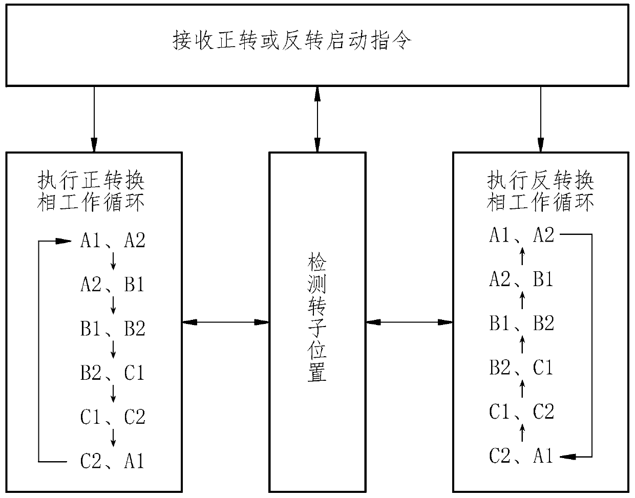
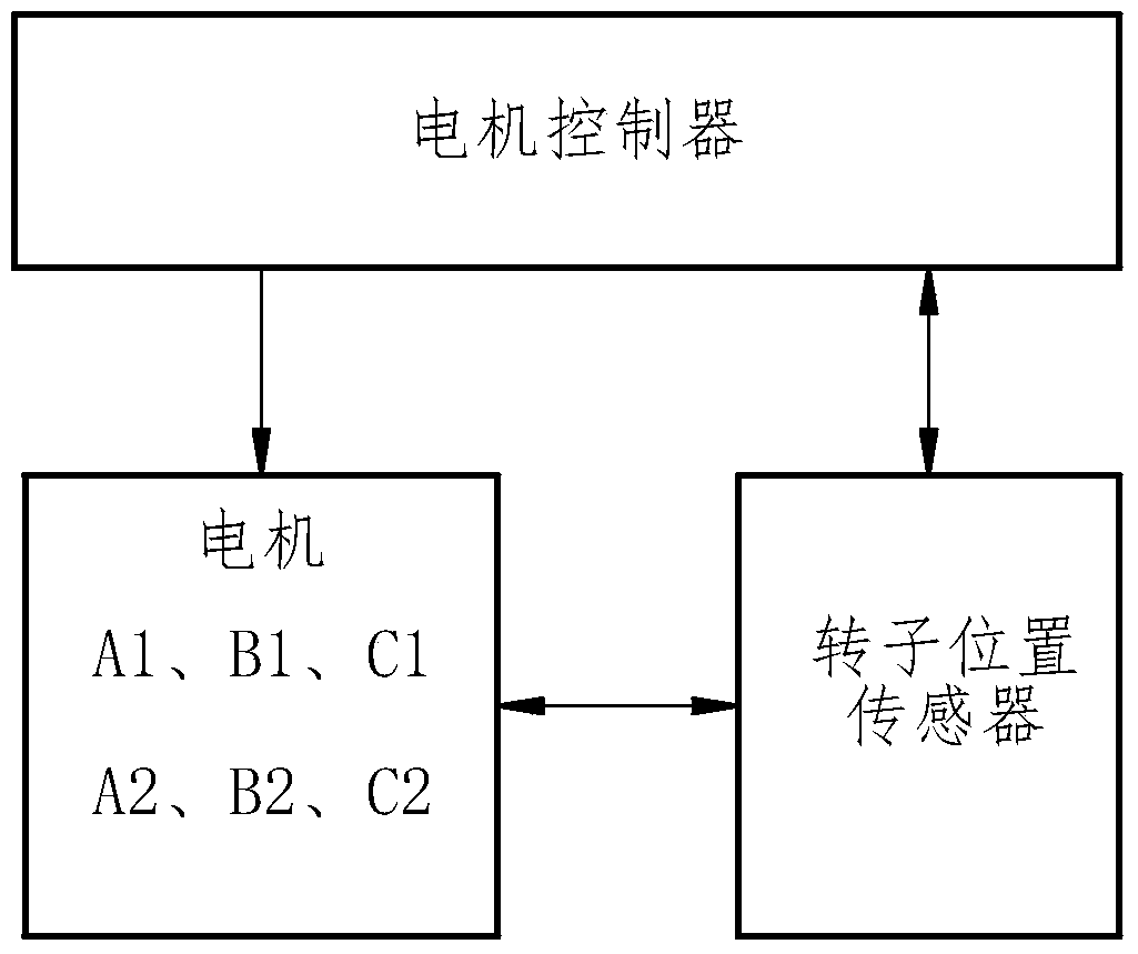
[0020] in figure 1 , figure 2 In the first embodiment shown, a method for controlling a circumferential and axial mixed phase switched reluctance motor, the circumferential and axial mixed phase switched reluctance motor has a 2×3 phase structure with two stator cores The phase windings are respectively defined as A1 phase, B1 phase, C1 phase and A2 phase, B2 phase, C2 phase, including the following steps: the motor controller receives the forward or reverse start command; the rotor position sensor detects the rotor position, and the rotor position The information is fed back to the motor ...


PUM


Abstract

The invention discloses a circumferential and axial mixing phase distribution switch reluctance motor control method. A circumferential and axial mixing phase distribution switch reluctance motor is a 2*3 phase or 3*2 phase or 2*2 phase structure. The method comprises the following steps of receiving a forward-rotating or reverse-rotating starting instruction; detecting a rotor position; and executing a forward-rotating transition phase work circulation or a reverse-rotating transition phase work circulation, wherein stator cores take turns to carry out transition phase. In the method, 2*3 phase and 3*2 phase structure motors realize 6 phase control through transition phase among the stator cores by turns; and a 2*2 phase structure motor realizes 4 phase control through the transition phase among the stator cores by turns. The phase number is increased, an effect pole number is not reduced, during a transition phase process, each related broken angle can be advanced, motor operation is smooth so that a torque pulsation and noises are improved, and the method is mainly applied in the switch reluctance motor field.

Description

Technical field [0001] The invention relates to the field of control methods for switched reluctance motors, and in particular to a control method for switched reluctance motors with mixed phase distribution in the circumferential direction and axial direction. Background technique [0002] The current switched reluctance motors mainly have the problems of torque ripple and noise, and there are certain reasons from the structural analysis. Taking the most commonly used 3-phase switched reluctance motor as an example, the salient poles of the rotor go from the active position to the position of the saliency of the stator. , The tangential force changes from a large value to zero, and the radial force changes from a small value to a maximum value. The change in the amplitude of the tangential force mainly affects the torque ripple, and the change in the amplitude of the radial force mainly affects the noise, especially at low speeds. , The working end of the salient pole of the rot...

Claims


Application Information

Patent Timeline
Patent Type & Authority Patents(China)
IPC IPC(8): H02P25/08H02P25/098H02P25/086
CPCH02P25/08
Inventor 顾志强李运忠
Owner SHENZHEN HUAYIN POWER TECH CO LTD
Why Eureka
Try Eureka