Quantum encryption microwave relay communication system and quantum encryption microwave relay communication method

A microwave relay, quantum encryption technology, applied in key distribution

Inactive Publication Date: 2016-08-31
ANHUI QASKY QUANTUM SCI & TECH CO LTD
View PDF3 Cites 8 Cited by
  • Summary
  • Abstract
  • Description
  • Claims
  • Application Information

AI Technical Summary

Problems solved by technology

The quantum key relay is different from the microwave station data relay. The microwave station relay is to amplify and forward the signal. The quantum key relay is the relay of the key. They need to be combined to complete the encryption protection of the data relay process. There is no relay scheme for quantum keys in the existing microwave communication technology

Method used


Image

  • Quantum encryption microwave relay communication system and quantum encryption microwave relay communication method
  • Quantum encryption microwave relay communication system and quantum encryption microwave relay communication method
  • Quantum encryption microwave relay communication system and quantum encryption microwave relay communication method

Examples


Embodiment 1

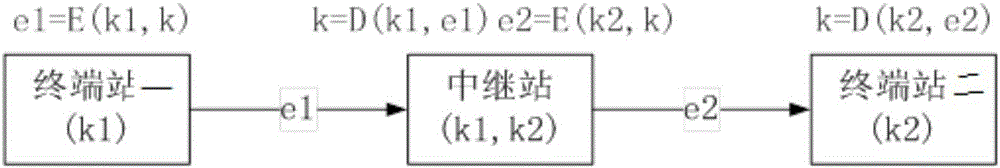
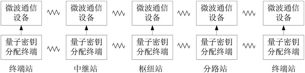
[0021] Such as figure 2 As shown in Fig. 3, this quantum encryption microwave relay communication system includes terminal station one, relay station and terminal station two; terminal station one, relay station and terminal station two are all made up of microwave communication equipment and quantum key distribution terminal; terminal station one It is used to use the key k1 to encrypt the key k to generate the key e1, e1=E(k1,k), and send the key e1 to the relay station; the relay station is used to use the key k1 to decrypt the key e1 Generate a key k, k=D(k1, e1), and use the key k2 to encrypt the key k to generate a key e2, e2=E(k2, k), and the relay station is also used to send the key e2 to Terminal station two; terminal station two is used to use key k2 to decrypt key e2 to generate key k, k=D(k2, e2); key k1 is generated by terminal station one and relay station through quantum key distribution terminal ; The key k2 is generated by the terminal station 2 and the rel...

Embodiment 2

[0023] see figure 2 , the quantum encryption microwave relay communication method, comprising a terminal station one, a relay station and a terminal station two; the terminal station one, the relay station and the terminal station two are all composed of microwave communication equipment and a quantum key distribution terminal; including the following steps:

[0024] 1) The terminal station 1 and the relay station produce the same key k1 through the quantum key distribution terminal;

[0025] 2) The terminal station 2 and the relay station produce the same key k2 through the quantum key distribution terminal;

[0026] 3) When terminal station 1 has key k and needs to be delivered to terminal station 2, first terminal station 1 uses key k1 to encrypt key k to generate key e1, e1=E(k1,k), and then terminal station - send the key e1 to the relay station;

[0027] 4) The relay station uses the key k1 to decrypt the key e1 to generate a key k, k=D(k1, e1), and the relay station ...


PUM


Abstract

The invention discloses a quantum encryption microwave relay communication system and a quantum encryption microwave relay communication method. The system comprises a terminal station I, a relay station, and a terminal station II. The terminal station I is used for performing encryption operation on a key k with a key k1 to generate a key e1 and sending the key e1 to the relay station. The relay station is used for performing decryption operation on the key e1 with the key k1 to generate the key k, performing encryption operation on the key k with a key k2 to generate a key e2, and sending the key e2 to the terminal station II. The terminal station II is used for performing decryption operation on the key e2 with the key k2 to generate the key k. The key k1 is generated by the terminal station I and the relay station through a quantum key distribution terminal. The key k2 is generated by the terminal station II and the relay station through the quantum key distribution terminal. Finally, the terminal station I and the terminal station II have the same key k. The key k is relayed through the process. Through key relay transfer, transfer of the key k from the terminal station I to the terminal station II is realized.

Description

technical field [0001] The present invention relates to a relay communication system and method, in particular to a quantum encryption microwave relay communication system and method. Background technique [0002] Since the main mode of microwave communication is line-of-sight communication, relaying is required after the line-of-sight is exceeded. Generally speaking, due to the influence of the curved surface of the earth and the loss of space transmission, it is necessary to set up relay stations at certain distances to amplify and forward radio waves to extend them. This communication method is also called microwave relay communication or microwave relay communication. A complete long-distance transmission microwave system consists of terminal stations, hub stations, branch stations and several relay stations. Quantum optical free space transmission is also line-of-sight communication. When the loss of space transmission is too large, key relay is also required, such as ...

Claims


Application Information

Patent Timeline
Patent Type & Authority Applications(China)
IPC IPC(8): H04L9/08
CPCH04L9/0852H04L9/0855
Inventor 苗春华张启发王立霞吕利影刘云赵义博韩正甫
Owner ANHUI QASKY QUANTUM SCI & TECH CO LTD
Why Eureka
Try Eureka