Supercharge Your Innovation With Domain-Expert AI Agents!

Moving Picture Encoding Device, Moving Picture Encoding Method And Moving Picture Encoding Program As Well As Moving Picture Decoding Device, Moving Picture Decoding Method And Moving Picture Decoding Program

The technology of a decoding device and a decoding method is applied in the field of moving image decoding device and moving image decoding, and can solve problems such as the problem of the code amount of the coding vector

Active Publication Date: 2016-08-31
JVC KENWOOD CORP
View PDF2 Cites 3 Cited by
  • Summary
  • Abstract
  • Description
  • Claims
  • Application Information

AI Technical Summary

Problems solved by technology

But on the other hand, because the block size is reduced, the number of motion vectors will increase, so the code size of the coded vector becomes a problem

Method used


Image

  • Moving Picture Encoding Device, Moving Picture Encoding Method And Moving Picture Encoding Program As Well As Moving Picture Decoding Device, Moving Picture Decoding Method And Moving Picture Decoding Program
  • Moving Picture Encoding Device, Moving Picture Encoding Method And Moving Picture Encoding Program As Well As Moving Picture Decoding Device, Moving Picture Decoding Method And Moving Picture Decoding Program
  • Moving Picture Encoding Device, Moving Picture Encoding Method And Moving Picture Encoding Program As Well As Moving Picture Decoding Device, Moving Picture Decoding Method And Moving Picture Decoding Program

Examples


no. 1 Embodiment approach

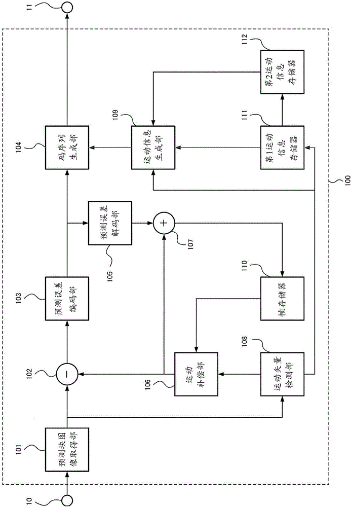
[0112] (Structure of the moving picture encoding device 100)

[0113] figure 1 The configuration of the moving picture encoding device 100 according to the first embodiment of the present invention is shown. The moving picture coding device 100 is a device for coding a moving picture signal in units of prediction blocks to which motion compensation prediction is performed. The coding block division, prediction block size, and prediction coding mode are determined by a high-level coding control unit. The moving picture encoding device 100 is realized by hardware such as an information processing device including a CPU (Central Processing Unit), a frame memory, a hard disk, and the like. The moving picture encoding device 100 realizes the functional constituent elements described below by the operations of the above constituent elements.

[0114] In addition, the position information of the prediction block to be processed, the prediction block size, the reference picture ind...

no. 2 Embodiment approach

[0277] Figure 21 The configuration of the moving picture encoding device 300 according to the second embodiment of the present invention is shown. In addition to the setting of the terminal 30, the motion information compression unit 301, the second motion information memory 302, the motion information decompression unit 303, and the motion information generation unit 109, the configuration of the moving picture encoding device 300 according to the second embodiment of the present invention is The configuration is the same as that of the video encoding device 100 of the first embodiment.

[0278] Next, differences between the settings of the terminal 30 and the functions of the motion information compression unit 301, the second motion information memory 302, the motion information decompression unit 303, and the motion information generation unit 109 in this embodiment and the first embodiment will be described.

[0279] The motion information storage compression rate α and...


PUM


Abstract

A first vector predictor candidate list generating unit generates a first motion vector predictor candidate list from motion vectors of encoded neighboring blocks to blocks to be encoded. A second vector predictor candidate list generating unit generates a second motion vector predictor candidate list from motion vectors of blocks at the same positions as the blocks to be encoded in an encoded image and neighboring blocks to the blocks at the same positions. A combination determining unit determines whether to generate a third vector predictor candidate list combining the first and second vector predictor candidate lists by comparison of a block size of the blocks to be encoded and a threshold size. A vector predictor candidate list deciding unit generates the third vector predictor candidate list from the first vector predictor candidate list.

Description

[0001] This application is based on the application number 201280012382.9, the application date is March 05, 2012, the applicant is JVC Kenwood Co., Ltd., and the invention name is "moving picture coding device, moving picture coding method and moving picture coding program, and moving picture decoding Device, moving picture decoding method and moving picture decoding program" is a divisional application. technical field [0002] The present invention relates to a technique for encoding and decoding moving pictures using motion compensation prediction, and more particularly to a technique for encoding and decoding motion vectors used in motion compensation prediction. Background technique [0003] In general video compression coding, motion compensation prediction is used. Motion compensation prediction is a technology that divides the target image into smaller blocks, uses the decoded image as a reference image, and shifts the block from the same position as the target bloc...

Claims


Application Information

Patent Timeline
Patent Type & Authority Applications(China)
IPC IPC(8): H04N19/105H04N19/176H04N19/70H04N19/513H04N19/134H04N19/61
Inventor 竹原英树上田基晴西谷胜义中村博哉坂爪智荒荫和美福岛茂熊仓徹
Owner JVC KENWOOD CORP
Features
  • R&D
  • Intellectual Property
  • Life Sciences
  • Materials
  • Tech Scout
  • Unparalleled Data Quality
  • Higher Quality Content
  • 60% Fewer Hallucinations
Learn More