Caster structure of fishing line reel

A fishing reel and caster technology, which is applied to fishing reels, fishing, applications, etc., can solve the problem of inability to adjust the size of the force arm, and achieve the effects of novel structure, improved fishing fun, and clever design.

Active Publication Date: 2016-09-07
慈溪市鱼乐渔具有限公司
View PDF10 Cites 0 Cited by
  • Summary
  • Abstract
  • Description
  • Claims
  • Application Information

AI Technical Summary

Problems solved by technology

[0003] In order to solve the above-mentioned technical problem that the size of the moment arm cannot be adjusted, the present invention provides a fishing reel caster structure

Method used


Image

  • Caster structure of fishing line reel
  • Caster structure of fishing line reel
  • Caster structure of fishing line reel

Examples


Embodiment 1

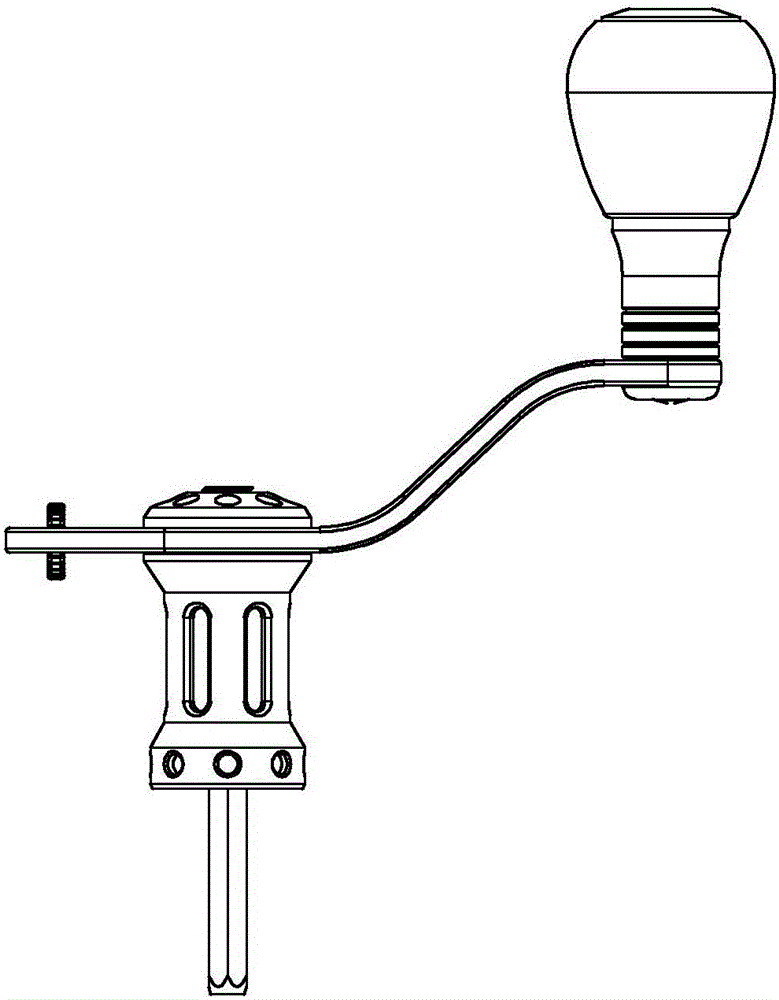
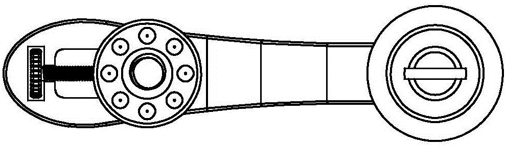
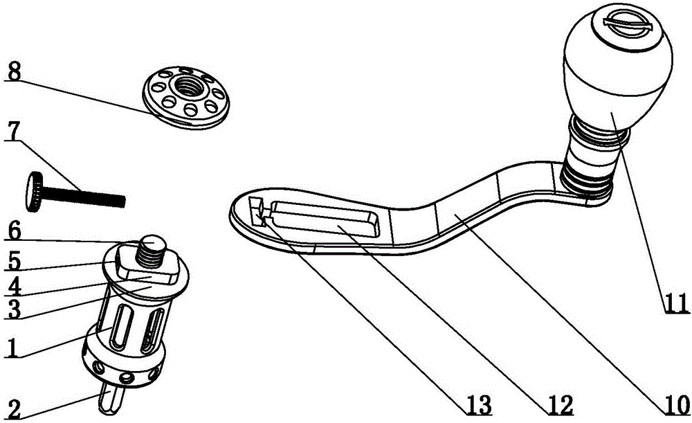
[0020] Such as figure 1 , 2 The fishing line wheel caster structure shown in 3 includes a rotating rod 2 inserted into a gear plate and a bracket 10. The rotating rod 2 is connected to one end of the bracket 10 through a mounting base 1, and the surface of the mounting base 1 is provided with a smooth mounting surface 3. , The mounting surface 3 is provided with a bump 4 conveniently, the other end of the bracket 10 is provided with casters 11, and the mounting seat 1 and the bracket 10 are provided with a moment arm adjustment structure.

[0021] The force arm adjusting structure includes a protrusion 4 provided on the surface of the mounting seat 1, an adjusting screw 7 is penetrated inside the protrusion 4, a threaded through hole 5 is horizontally provided inside the protrusion 4, an inner wall of the threaded through hole 5 and an adjusting screw 7 The tooth pattern of the bracket 10 is opposite. One end of the bracket 10 is provided with a movable slot 12 and a card slot 13....

Embodiment 2

[0024] Such as Figure 4 , 5 As shown, the difference between this embodiment and Embodiment 1 is that the force arm adjusting structure includes a clamping block 15 provided on the surface of the mounting base 1, a clamping slot 14 is provided on one end of the bracket 10, and the clamping block 15 is inserted into the clamping position. The slot 14 is installed on the bracket 10, the number of the locking slot 14 is three, the surface of the locking block 15 is provided with a screw 6, and the screw 6 passes through the locking slot 14 and is connected to the nut 8.

[0025] When in use, there are a plurality of locking slots 14, which are arranged in sequence along the bracket 10. The locking slots 14 close to or far from the casters 11 can be selected to adjust the size of the arm.

Embodiment 3

[0027] Such as Image 6 , 7 As shown, the force arm adjustment structure includes a protrusion 4 provided on the surface of the mounting seat 1, a sliding rod 16 is penetrated inside the protrusion 4, a movable chute 17 is provided at one end of the bracket 10, and both ends of the sliding rod 16 are fixed in the movable On both sides of the sliding groove 17, the middle of the surface of the protrusion 4 is hollowed out to form a hole 19, and a fixing screw 20 is installed in the hole 19. The fixing screw 20 contacts the sliding rod 16 and is pressed and fixed.

[0028] When using, first select the position of the protrusion 4 on the sliding rod 16, and then install the fixing screw 20 so that the fixing screw 20 tightly presses the sliding rod 16 to fix. The distance between the protrusion 4 and the casters 11 is adjusted by adjusting the protrusion The position of the block 4 on the slide bar 16 is changed.


PUM


Abstract

The invention relates to the field of fishing gears, in particular to a caster structure of a fishing line reel. The caster structure comprises a rotary bar and a support, wherein the rotary bar is inserted into a fluted disc and connected with one end of the support through a mounting seat, and a caster is arranged at the other end of the support; a force arm adjusting structure is arranged on the mounting seat and the support. The caster structure has the benefits as follows: various forms are realized, the distance between the rotary bar and the caster can be adjusted through rotation of a movable round head, by clamping grooves at different distances or through adjustment of the front and back position on a sliding bar, and the size of the force arm is adjusted; according to the principle of force, force is inversely proportional to the force arm, and the larger the force arm is, the smaller the force is, so that a user can perform adjustment as required, the fishing fun is increased, and the caster structure is convenient, practical, novel in structure and ingenious in design.

Description

technical field [0001] The invention relates to the field of fishing gear, in particular to the caster structure of a fishing reel. Background technique [0002] Nowadays, amateur life is becoming more and more extensive, and fishing is becoming more and more popular. At present, the fishing reel we use drives the tooth plate through the rotating rod to make the movable rod move up and down. The rotating rod is fixedly connected with the bracket, so the rotating rod cannot be adjusted. The distance between the rod and the casters, that is, the length of the arm of force cannot be adjusted, and in fishing for special fish species, the magnitude of the force cannot be changed, which is inconvenient to use. Contents of the invention [0003] In order to solve the above-mentioned technical problem that the size of the moment arm cannot be adjusted, the present invention provides a caster structure of the fishing reel. [0004] Technical scheme of the present invention is as f...

Claims


Application Information

Patent Timeline
Patent Type & Authority Applications(China)
IPC IPC(8): A01K89/00
Inventor 陆开冬
Owner 慈溪市鱼乐渔具有限公司
Why Eureka
Try Eureka