
Head support for PET/CT (positron emission computed tomography) scanning bed

A scanning bed and head support technology, which is applied in the fields of radiological diagnosis instruments, computed tomography scanners, applications, etc., can solve the problems of inability to guarantee the scanning image of the eyebrow line, affecting the normal diagnosis of doctors, and easy movement of patients, etc. To achieve the effect of clear brain tissue structure, good display and effective support

Active Publication Date: 2016-09-07
FMI MEDICAL SYST CO LTD
View PDF6 Cites 1 Cited by
  • Summary
  • Abstract
  • Description
  • Claims
  • Application Information

AI Technical Summary

Problems solved by technology

[0004] The technical problem solved by the present invention is that in the prior art, most of the PET / CT scanning process needs to last 10 to 30 minutes, and the head, neck, and arms lack strong support and support, which makes it difficult for patients to Keep this posture until the end of the scan, and the patient is prone to move due to discomfort during the scan, and it cannot be guaranteed that when the brow line is used as the scan baseline, this line is basically perpendicular to the horizontal plane of the diagnostic bed / scanning bed, which will cause artifacts in the scanned image and affect the doctor The problem of normal diagnosis, and then provides a headrest for PET / CT scanning table with an optimized structure

Method used


Image

  • Head support for PET/CT (positron emission computed tomography) scanning bed
  • Head support for PET/CT (positron emission computed tomography) scanning bed
  • Head support for PET/CT (positron emission computed tomography) scanning bed

Examples


Embodiment Construction

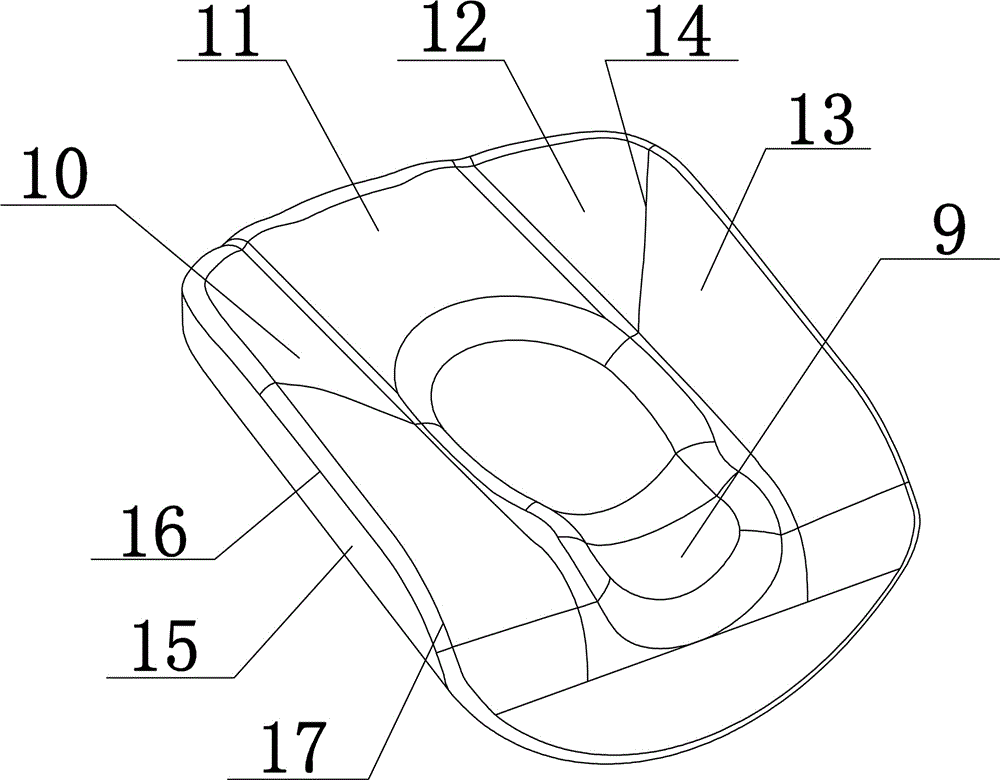
[0027] The present invention will be further described in detail below in conjunction with embodiments, but the protection scope of the present invention is not limited thereto.

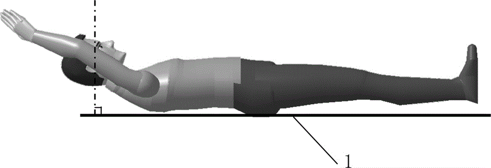
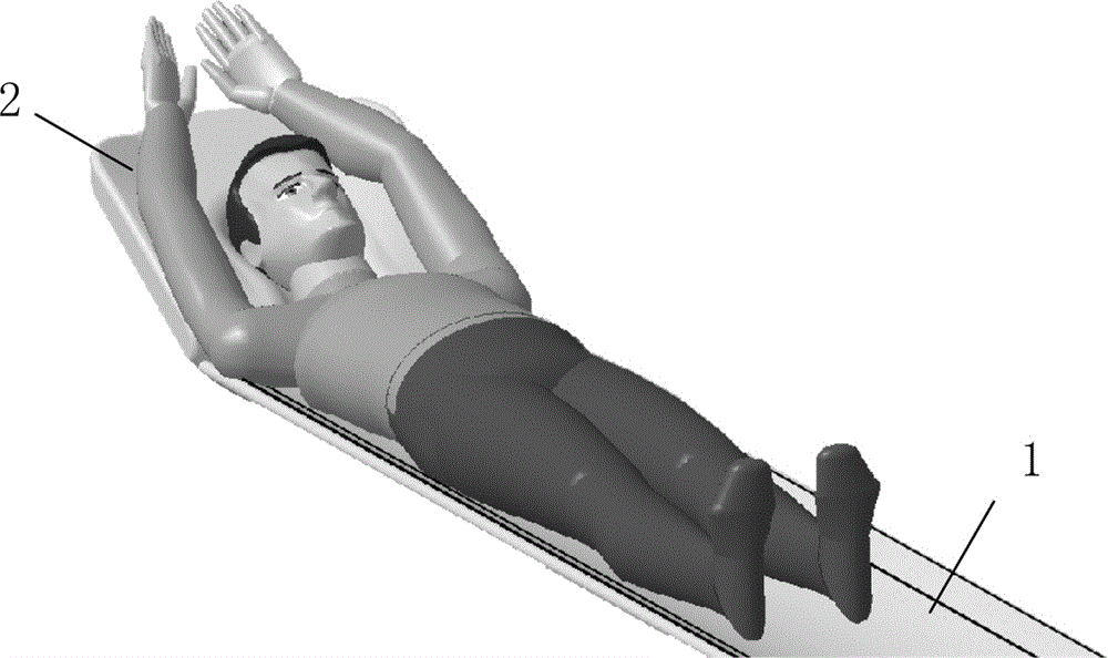
[0028] Such as Figure 2-4 As shown, figure 2 For the posture requirements of PET / CT scanning, the dotted line is the earbrow line (EML), image 3 with 4 The side view and schematic diagram of the patient's posture during PET / CT scanning using the embodiment provided by the present invention.

[0029] As shown in the figure, the present invention relates to a head rest for a PET / CT scanning bed, including a head rest 2 body set on the scanning bed 1, the head rest 2 includes a support 3, the support 3 includes The bed 1 is connected by a locking device 4 with a positioning plate 5, a headrest plate 6 arranged upward at an angle to the positioning plate 5, and two headrest plates 6 arranged on both sides of the headrest 6 and facing upward at an angle to the headrest 6 Support arm plate 7; the outer side...


PUM

PropertyMeasurementUnit
Radiusaaaaaaaaaa
Angleaaaaaaaaaa

Abstract

The invention relates to a head support for a PET / CT (positron emission computed tomography) scanning bed. The head support comprises a head support body which is arranged on the scanning bed and comprises a bracket, wherein the bracket comprises a positioning plate connected with the scanning bed by virtue of a locking device, a head support plate which forms an upward angle with the positioning plate and two arm support plates; the two arm support plates are positioned on two sides of the head support plate and form upward angles with the head support plate; the outer sides of the head support plate and the arm support plates are wrapped with an integrally-molded head pillow. The relative positions of the head support and the scaning bed are defined, so that the influence of the abnormal status of a patient head is reduced, the image scanning quality is improved, the body posture requirements of the patient during PET / CT scanning are met, an included angle between the EML of the patient and the horizontal surface of the scanning bed is within a range of 90+ / -5 degrees, so that relatively clear brain tissue structures can be obtained in scanned images, especially the display of a subtentorial fourth ventricle and a supratentorial basal ganglia is favorable; meanwhile, both arms of the patient are effectively supported, and the comfort degree is increased.

Description

Technical field [0001] The present invention belongs to the technical field of instruments used for radiological diagnosis, such as instruments combined with radiotherapy equipment, and particularly relates to a method for stably supporting and fixing the patient’s head during medical imaging to make the patient’s eyebrow line (EML) ) Headrest for PET / CT scanning bed with an angle within the range of 90°±5° from the horizontal plane of the hospital bed. Background technique [0002] PET / CT (Positron Emission Computed Tomography) is a nuclear medicine imaging device that uses positron technology and human molecular information to obtain the functional metabolism of the lesion and the positioning information of the precise anatomical structure at the same time. The diagnosis and treatment of tumors, heart, and brain diseases play an important role. [0003] When using PET / CT to scan a patient, the patient is required to lie supine on the diagnostic bed / scanning bed, raise both arms ...

Claims


Application Information

Patent Timeline
IPC IPC(8): A61B6/04A61B6/03
CPCA61B6/035A61B6/037A61B6/0421A61B6/501
Inventor 金坚诚马兴江王强叶宏伟胡玮颜建华
Owner FMI MEDICAL SYST CO LTD
Learn More