
U-shaped piece grading punch forming die

A stamping forming and progressive technology, applied in forming tools, manufacturing tools, metal processing equipment, etc., can solve the problems of easy damage of the lower die block, difficult removal of parts, and low processing efficiency, so as to reduce the number of machines and personnel, The effect of ensuring machining accuracy and improving production efficiency

Active Publication Date: 2016-09-07
苏州金鸿顺汽车部件股份有限公司
View PDF4 Cites 6 Cited by
  • Summary
  • Abstract
  • Description
  • Claims
  • Application Information

AI Technical Summary

Problems solved by technology

Traditional processing uses engineering molds for single-piece stamping, which has low processing efficiency, and because of the narrow width of the parts, the lower die blades are easily damaged. In addition, the parts are not easy to take out after chamfering, and debugging is inconvenient

Method used


Image

  • U-shaped piece grading punch forming die
  • U-shaped piece grading punch forming die
  • U-shaped piece grading punch forming die

Examples


Embodiment Construction

[0028] Specific embodiments of the present invention will be described in detail below in conjunction with the accompanying drawings.

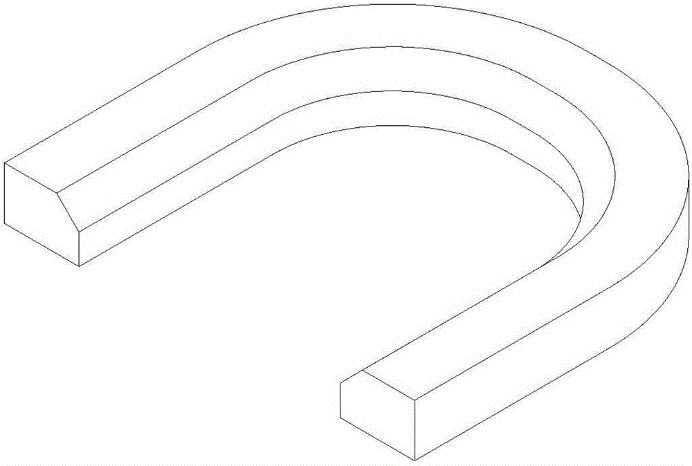
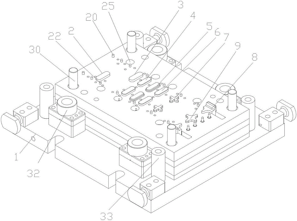
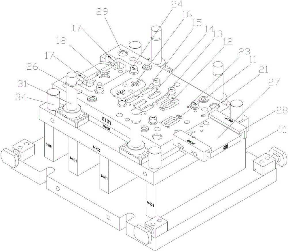
[0029] Such as Figure 2-4 As shown, a progressive stamping die for a U-shaped piece includes an upper die and a lower die. The upper mold includes an upper mold base 1, and the upper mold base 1 is sequentially provided with a waist-shaped left punch 2 and a right punch with the same shape as the left punch 2 from the feed end. Head 3, a pair of first positioning blocks 4 with the same shape as the left punch 2, a pair of waist-shaped hole-shaped forming punches 5, a pair of second positioning blocks 6 with the same shape as the left punch 2 , A pair of small cross punches 7, Dividing punch group. The distance between the left punch 2 and the right punch 3 along the feeding direction is two feeding lengths, the distance between the first positioning block 4 and the forming punch 5, and the distance between the forming punch 5 and the second...


PUM


Abstract

The invention discloses a U-shaped piece grading punch forming die with high production efficiency. The U-shaped piece grading punch forming die comprises an upper die and a lower die, wherein the upper die comprises an upper die holder; a kidney-shaped hole shaped left piercing punch, a right piercing punch, a pair of a first positioning blocks, a pair of kidney-shaped hole shaped forming punches, a pair of a second positioning blocks, a pair of cross-shaped punches and a material dividing punch group are sequentially arranged on the upper die holder starting from the feeding end; the left piercing punch has the same shape as the right piercing punch, the first positioning blocks and the second positioning blocks; the material dividing punch group comprises two T-shaped punches and a large cross-shaped punch; the two T-shaped punches are perpendicular to the feeding direction and are in a straight line; the large cross-shaped punch is arranged between the two T-shaped punches; the lower die comprises a lower die holder; corresponding left piercing groove, a right piercing groove, a pair of first positioning grooves, a pair of forming grooves, a pair of second positioning grooves, a pair of small cross-shaped grooves and a material dividing groove group are sequentially formed in the lower die holder starting from the feeding end; the material dividing groove group comprises two T-shaped grooves and a large cross-shaped groove.

Description

technical field [0001] The invention relates to a U-shaped piece progressive stamping forming die. Background technique [0002] Various U-shaped parts stamped from sheet metal are widely used in the field of machinery, such as figure 1 The U-shaped piece shown is made by punching a plate, and the upper wall of the inner ring of the U-shaped piece needs to be chamfered and stamped. Traditional processing uses engineering molds for single-piece stamping, which has low processing efficiency, and due to the narrow width of the parts, the lower die blades are easily damaged. In addition, the parts are not easy to take out after chamfering, and debugging is inconvenient. Contents of the invention [0003] The technical problem to be solved by the present invention is to provide a U-shaped progressive stamping die with high production efficiency. [0004] In order to solve the above-mentioned technical problems, the technical solution adopted in the present invention is: a pro...

Claims


Application Information

Patent Timeline
Patent Type & Authority Applications(China)
IPC IPC(8): B21D37/08
CPCB21D37/08
Inventor 徐然丽
Owner 苏州金鸿顺汽车部件股份有限公司
Learn More