Method and device for starting a drive system of a motor vehicle

A technology for drive systems and motor vehicles, applied to the layout of power plant control mechanisms, control devices, vehicle components, etc., to achieve the effect of reducing the speed drop

Active Publication Date: 2020-07-03
MAN TRUCK & BUS AG
View PDF14 Cites 0 Cited by
  • Summary
  • Abstract
  • Description
  • Claims
  • Application Information

AI Technical Summary

Problems solved by technology

[0008] However, in the known method, an unresolved technical problem is that a drop in rotational speed can occur during actuation or switching of the PTO or a change in load demand, since the switching of the PTO (in particular in the case of commercial vehicles ) implies an additional load requirement, which can be extended until the engine is fully loaded (for example, in the case of concrete pumps or in the case of hydraulic pump drives)

Method used


Image

  • Method and device for starting a drive system of a motor vehicle
  • Method and device for starting a drive system of a motor vehicle

Examples


Embodiment Construction

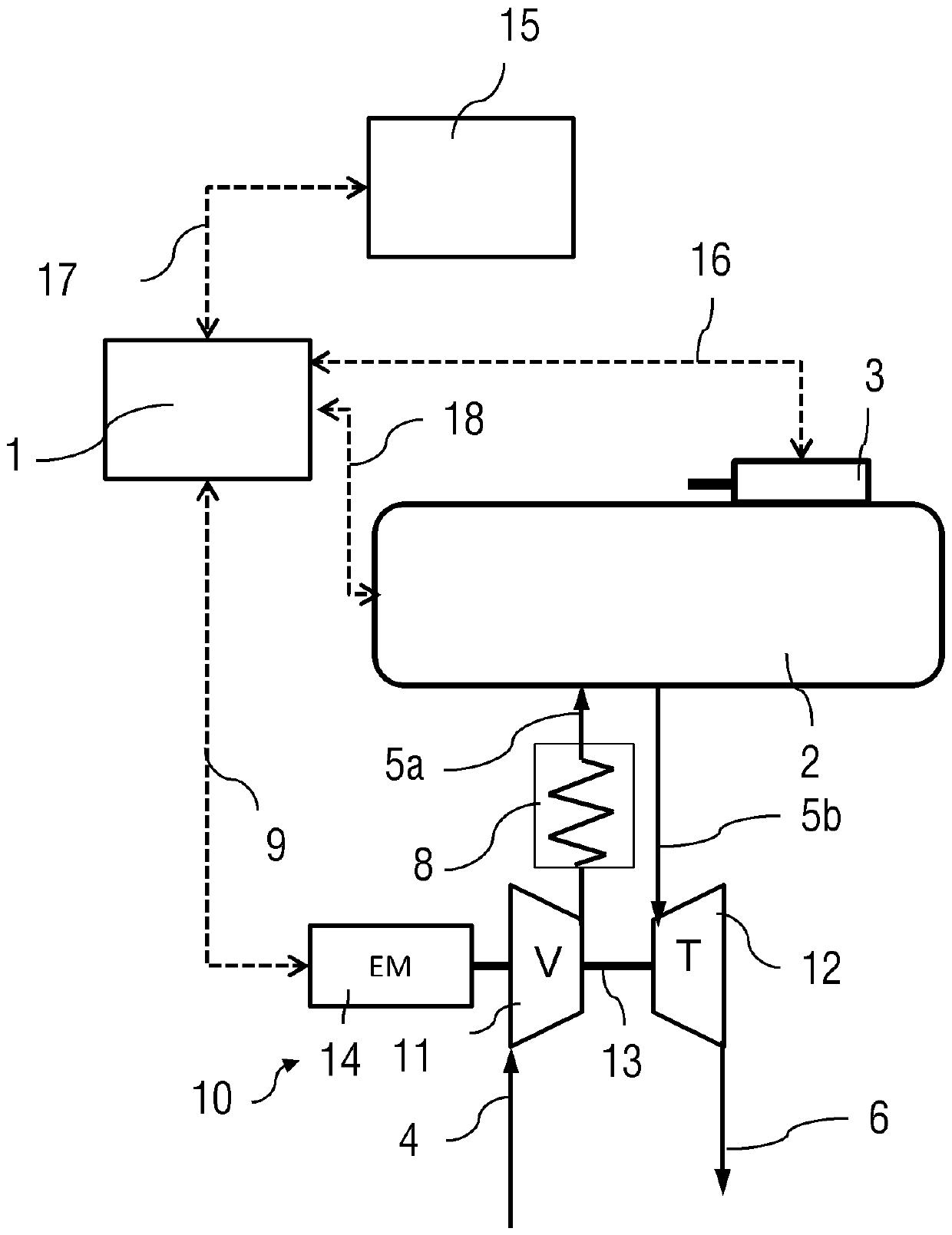
[0049] figure 1 The drive system of a commercial vehicle is shown in the form of a highly schematic block diagram. The drive system comprises a supercharged internal combustion engine 2 , usually a diesel engine, and an electrified exhaust-gas turbocharger 10 , hereinafter also referred to as ATL, assigned to it. The ATL 10 comprises a turbine 12 driven by the exhaust gases of the internal combustion engine 2 , which are fed to the turbine 12 via the exhaust line 5 b. Thereafter, the exhaust mixture flows via the turbine outlet into the exhaust line 6 to the exhaust port, and in doing so optionally also extends through an exhaust aftertreatment device (not shown).

[0050] The turbine 12 is connected to the compressor 11 by a shaft 13 . Fresh air is fed to the compressor 11 via the compressor inlet line 4 . The compressor 11 compresses charge air to be fed to the internal combustion engine 2 and thus increases the power output of the internal combustion engine 2 during norm...


PUM


Abstract

The invention relates to a method and a device for starting a drive system of a motor vehicle. In particular, the invention relates to a method for starting a drive system of a motor vehicle, in particular a commercial vehicle, having an internal combustion engine supercharged by an electrified exhaust-gas turbocharger and an engine-side or transmission-side power take-off. According to a general aspect of the present invention, the electric motor operation of the electrified exhaust gas turbocharger is started in a manner depending on the operating state of the power take-off in order to more quickly provide the increased power output required by the power take-off. In this way, a drop in rotational speed caused by the power take-off demand of the power take-off can be avoided or at least reduced.

Description

technical field [0001] The invention relates to a method for starting a drive system of a motor vehicle, in particular a commercial vehicle, having an internal combustion engine charged by an electrified exhaust-gas turbocharger and an engine-side or transmission-side power take-off. Furthermore, the invention relates to a device designed to carry out such a method. Background technique [0002] It is known from practice that combustion engines (also generally referred to in this document as internal combustion engines), in particular of commercial vehicles, have one or more power take-offs (PTO), ie possibly for attaching auxiliary components. A consumer, such as a pump, compressor or similar auxiliary component, may be connected to the power take-off, which is then driven by the combustor. Especially in the field of commercial vehicles, corresponding add-ons or outputs are already provided for certain applications, such as bus engines or air-conditioning compressors in th...

Claims


Application Information

Patent Timeline
Patent Type & Authority Patents(China)
IPC IPC(8): B60K26/02B60K17/28F02B39/10F02B37/14
CPCB60K17/28B60K26/02F02B37/14F02B39/10F02B37/10B60Y2400/435B60W10/06B60W10/30B60W30/1888B60W2510/305B60W2710/0638B60W2710/305Y02T10/12
Inventor A.帕彭海默A.佐默曼
Owner MAN TRUCK & BUS AG
Why Eureka
Try Eureka