Feedback 3d printer

A 3D printer and feedback technology, applied in the field of 3D printing, can solve problems such as the inability to use a variety of raw materials and the inability to perform high-pressure rapid jet printing.

Active Publication Date: 2019-07-05
贵州云侠科技有限公司
View PDF12 Cites 0 Cited by
  • Summary
  • Abstract
  • Description
  • Claims
  • Application Information

AI Technical Summary

Problems solved by technology

[0005] The present invention provides a feedback type 3D printer aiming at the technical problems that existing 3D printers cannot use various raw materials and cannot perform high-pressure rapid jet printing.

Method used


Image

  • Feedback 3d printer
  • Feedback 3d printer
  • Feedback 3d printer

Examples


Embodiment 1

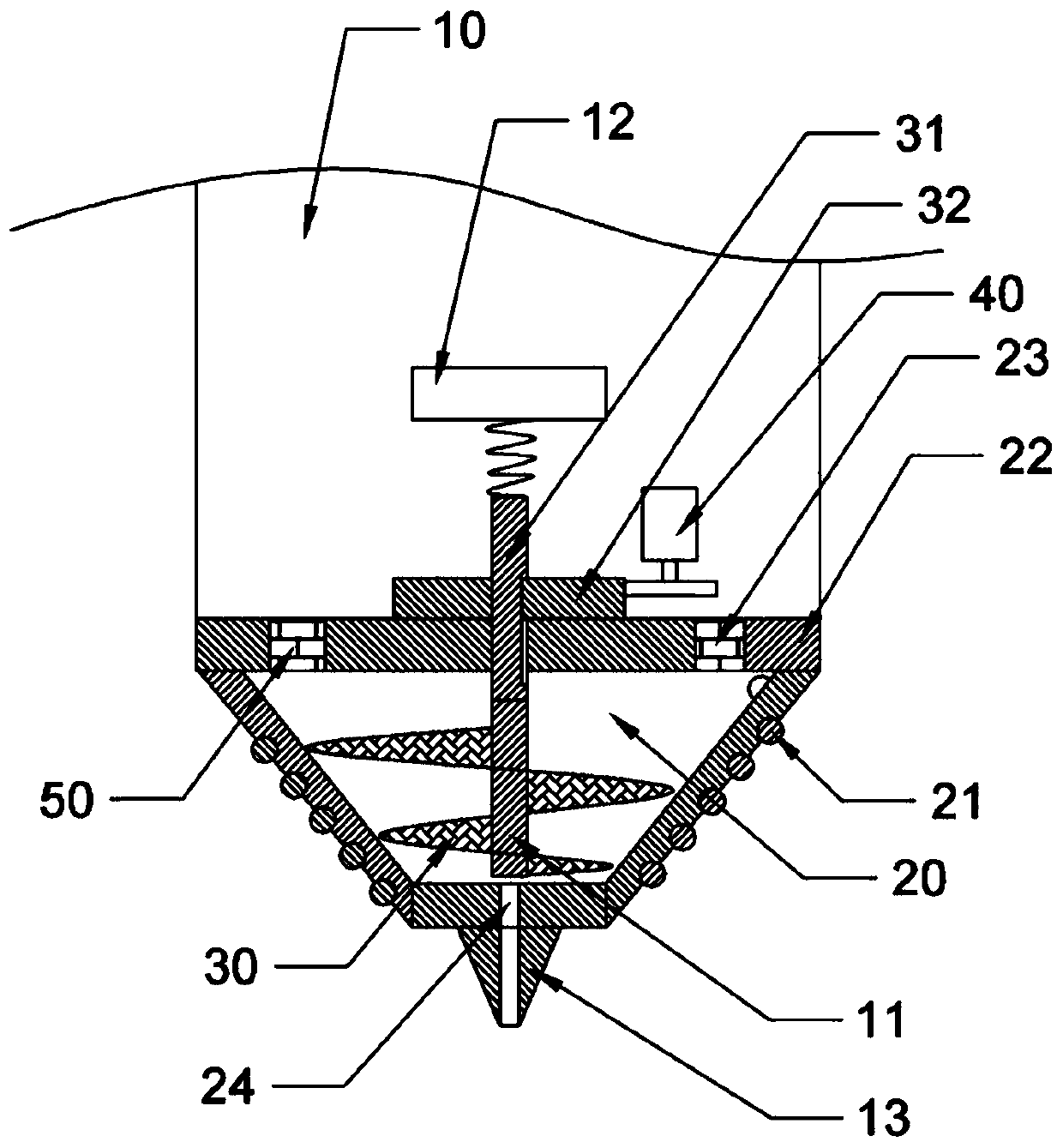
[0037] A feedback 3D printer, including a print head and a printer body for driving the print head to move in three-dimensional space;

[0038] print head (such as figure 1 shown) includes: a housing 10, a stirring shaft 11, an electromagnet 12, a nozzle 13, a temperature sensor and a controller; the material of the housing 10 is plastic. Specific spatial positions: from top to bottom are the electromagnet 12, the stirring shaft 11, and the nozzle 13.

[0039] The casing 10 is provided with a hot-melt part made of plastic material. The hot-melt part is provided with a conical hot-melt cavity 20 with a large upper part and a smaller lower part. The hot-melt part is covered with an electromagnetic heater 21. Above the hot-melt cavity 20 A sealing cover 22 is hinged, and a pressure relief valve 23 is arranged on the sealing cover 22 , and a material injection port 24 is opened at the bottom of the hot-melt part.

[0040] The stirring shaft 11 is welded with a spiral stirring bl...

Embodiment 2

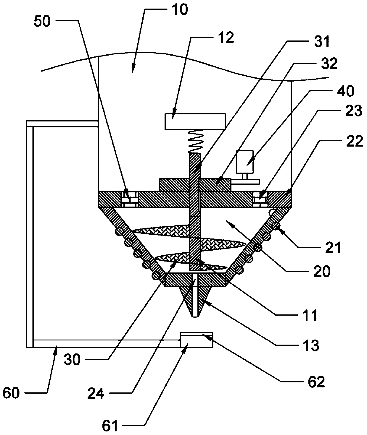
[0049] Compared with Embodiment 1, the only difference is that it also includes an air cooler 61 (such as figure 2 As shown), a bracket 60 is provided between the air cooler 61 and the shell, the air cooler 61 is located below the nozzle 13, and a pressure sensitive sensor 62 is arranged on the upper surface of the air cooler 61, and the pressure sensitive sensor 62 is connected to the controller signal.

[0050] Specific use: The raw material is cooled as soon as it comes out of the nozzle 13. When printing some bottom is a cavity and the upper part is a suspended structure (such as the roof of a house model), this design can speed up cooling and prevent collapse. . When there is a collapse, the raw material will fall on the surface of the air cooler 61, and the pressure sensitive sensor 62 can detect this signal and feed back to the controller. After the existing 3D printer fails to print, the print head will still move along the preset trajectory, resulting in waste of ra...


PUM


Abstract

The invention belongs to the technical field of 3D printing, and provides a feedback type 3D printer, aiming at solving the technical problems that various raw materials cannot be used, high-pressurefast jet printing cannot be performed by the existing 3D printer. The feedback type 3D printer includes a print head and a printer body for driving the print head to move in a three-dimensional space.The print head comprises a shell and a mixing shaft, wherein a hot melting part made of plastic is arranged in the shell; the hot melting part is provided with a circular truncated cone-shaped hot melting cavity with a large upper part and a small lower part; the hot melting part is covered with an electromagnetic heater; a sealing cover is arranged on the hot melting cavity; a pressure relief valve is arranged on the sealing cover; a material injection opening is formed in the bottom of the hot melting part; the mixing shaft is provided with spiral mixing blades; both the mixing shaft and the mixing blades are made of metal; the diameters of the mixing blades on the mixing shaft are gradually reduced; the mixing blades can also be in contact with the inner side face of the hot melting cavity simultaneously; a driving shaft is fixed to the top of the mixing shaft; the seal cover is provided with a through hole through which the driving shaft can pass; and driving teeth are arranged onthe driving shaft.

Description

technical field [0001] The invention relates to the field of 3D printing, in particular to a feedback 3D printer. Background technique [0002] 3D printing technology is a rapid prototyping technology, which is based on digital model files, using metal, plastic, inorganic materials, etc., to construct objects by layer-by-layer printing. At present, the 3D printing technology that uses plastic as the consumable mostly adopts the fused deposition method (FDM technology), that is, after the filamentous hot-melt material is melted, it is extruded through a nozzle and deposited on a platform, and finally formed by layer-by-layer accumulation of materials. object. [0003] However, due to the limitation of filamentary materials, it is difficult to realize the diversity of materials (that is, only filamentous materials can be used, and granular materials cannot be used). Also due to the limitation of filamentary materials, the pressure of material extrusion is directly provided by...

Claims


Application Information

Patent Timeline
Patent Type & Authority Patents(China)
IPC IPC(8): B29C64/106B29C64/118B29C64/295B29C64/314B29C64/393B33Y30/00B33Y40/00B33Y50/02
CPCB33Y30/00B33Y40/00B33Y50/02
Inventor 余洪科刘秋刘运镇
Owner 贵州云侠科技有限公司
Why Eureka
Try Eureka