Device and method for eliminating optical fiber cable feeding bubbles

A fiber optic cable and air bubble technology, which is applied in the field of optical fiber production, can solve the problems of high viscosity of coatings, easy generation of bubbles, and unguaranteed sensitivity, so as to ensure the performance of coatings and eliminate bubbles

Pending Publication Date: 2020-09-08
杭州金星通光纤科技有限公司
View PDF0 Cites 7 Cited by
  • Summary
  • Abstract
  • Description
  • Claims
  • Application Information

AI Technical Summary

Problems solved by technology

[0004] 1. Because the tonnage is too large, the viscosity of the paint is high, and the paint is used quickly. Many optical fiber manufacturers cannot achieve 36 hours of heating time. As a result, when the tonnage comes out of the oven, the bubbles cannot be completely eliminated.
[0005] 2. Due to the high viscosity of the paint, it is easy to generate air bubbles during the transportation process, and the natural elimination time is very long. The ton barrels are transported to the feeding equipment in the heating zone and the air bubbles cannot be avoided. The sensitivity of the air bubble detection device cannot be guaranteed. All the bubble paint was returned, resulting in part of the bubble-containing paint still being coated on the optical fiber, resulting in the failure of the environmental test of the optical fiber

Method used


Image

  • Device and method for eliminating optical fiber cable feeding bubbles
  • Device and method for eliminating optical fiber cable feeding bubbles
  • Device and method for eliminating optical fiber cable feeding bubbles

Examples


Embodiment Construction

[0025] The following will clearly and completely describe the technical solutions in the embodiments of the present invention with reference to the accompanying drawings in the embodiments of the present invention. Obviously, the described embodiments are only some, not all, embodiments of the present invention. Based on the embodiments of the present invention, all other embodiments obtained by persons of ordinary skill in the art without making creative efforts belong to the protection scope of the present invention.

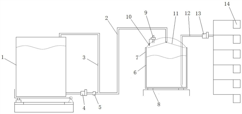
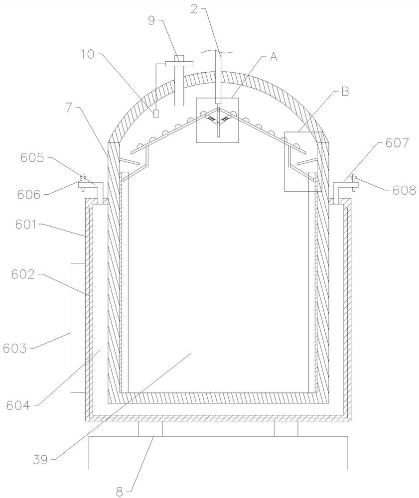
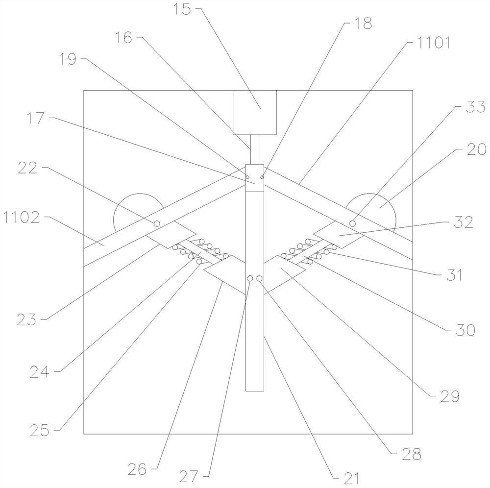
[0026] see Figure 1-4, in an embodiment of the present invention, a device for eliminating air bubbles in the optical fiber line, comprising a tote 1, a buffer tank 7 and a feeding tank 14, a transmission pipe 2 is connected between the tote 1 and the buffer tank 7, the The transmission pipe 2 is provided with a first diaphragm pump 4 and an air bubble detector 5, and between the air bubble detector 5 and the buffer tank 7 and on the transmission pipe 2 is co...


PUM


Abstract

The invention relates to a device for eliminating optical fiber cable feeding bubbles. The device is characterize in that a transmission pipe is connected between a ton barrel and a buffer tank; a first diaphragm pump and a bubble detector are arranged on the transmission pipe; a bubble reflux pipe communicated with the ton barrel is connected between the bubble detector and the buffer tank and ispositioned on the transmission pipe; an output pipe is connected between the buffer tank and a feeding tank; a second diaphragm pump is arranged on the output pipe; a weighing table is arranged at the lower end of the buffer tank; a water bath heating barrel is further arranged on the periphery of the buffer tank; a defoaming cavity is formed in the buffer tank; a vacuum pump control device is arranged at the upper end of the buffer tank and located in the defoaming cavity; a pressure detector electrically connected with the vacuum pump control device is further arranged in the defoaming cavity; the transmission pipe is connected with a feeding pipe in the defoaming cavity; and a flow divider is installed on the feeding pipe. The invention also discloses a method for eliminating optical fiber cable feeding bubbles. The invention aims to provide a scheme for reducing optical fiber coating bubbles, improve the percent of pass of optical fibers and reduce waste optical fibers.

Description

technical field [0001] The invention relates to the technical field of optical fiber production, in particular to a device and method for eliminating air bubbles in optical fiber wire supply. Background technique [0002] Existing solution: At present, the general-purpose communication optical fiber is coated twice to protect the mechanical performance and wear resistance of the optical fiber. At present, the large tank feeding system commonly used by major optical fiber manufacturers is: before use, the coating The inner-coated and outer-coated totes are placed in an oven for 36 hours to speed up the elimination of air bubbles generated by shaking during the process of purchasing and warehousing. When needed, transport the totes to the feeding area. After connecting the totes to the pipeline, use a diaphragm The pump pumps the paint to the small feeding tank (30kg) on ​​site. There is an air bubble inspection device between the diaphragm pump and the ton barrel. If bubbles ...

Claims


Application Information

Patent Timeline
Patent Type & Authority Applications(China)
IPC IPC(8): C03C25/1065C03C25/12B01D19/02
CPCB01D19/02C03C25/1065C03C25/12
Inventor 邓奋王灵通
Owner 杭州金星通光纤科技有限公司
Why Eureka
Try Eureka