
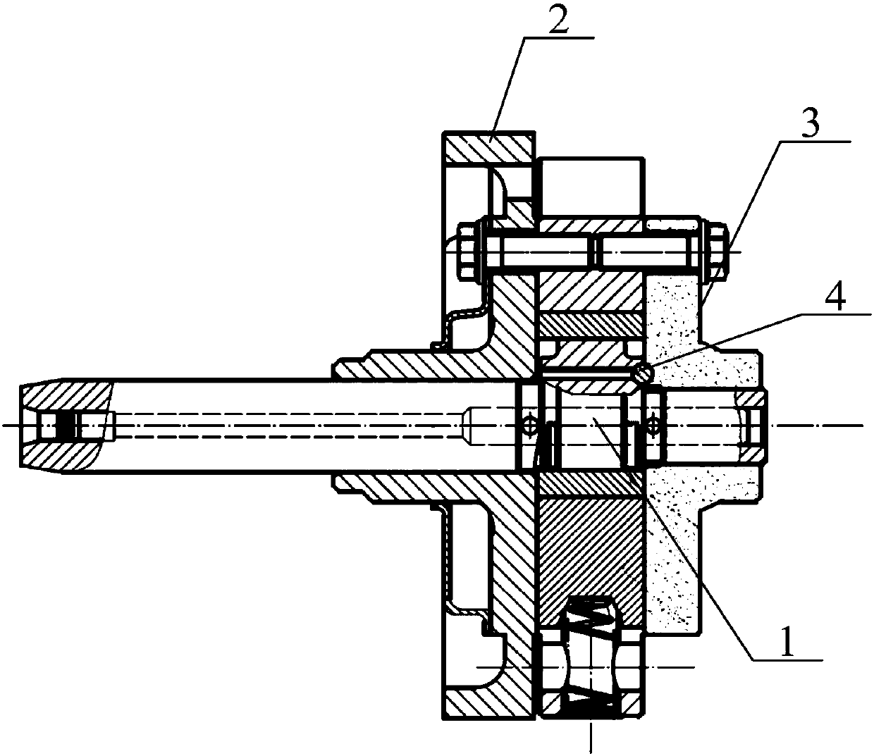
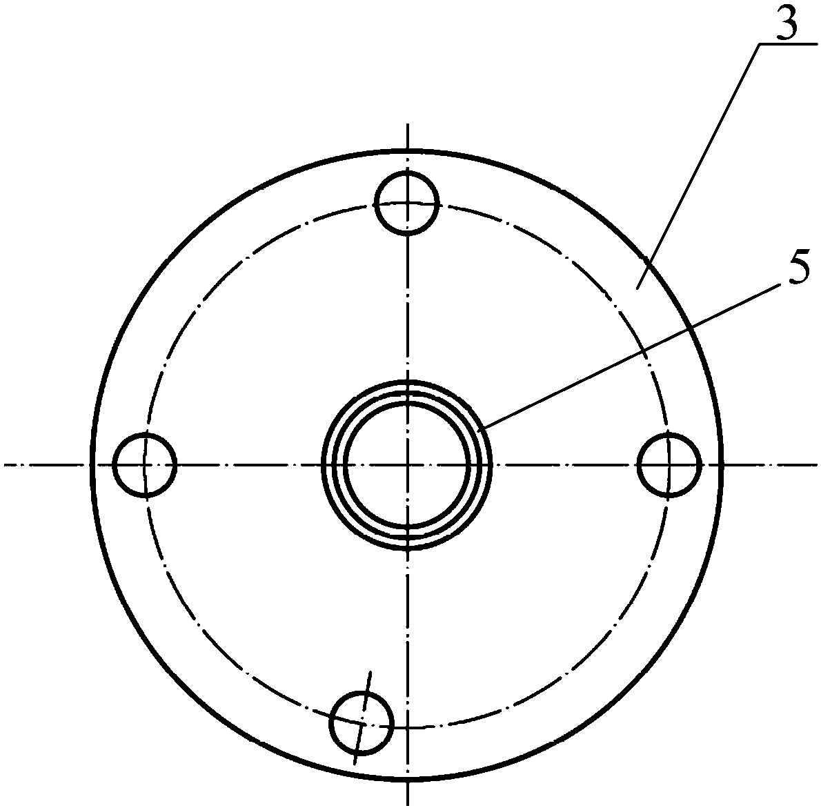
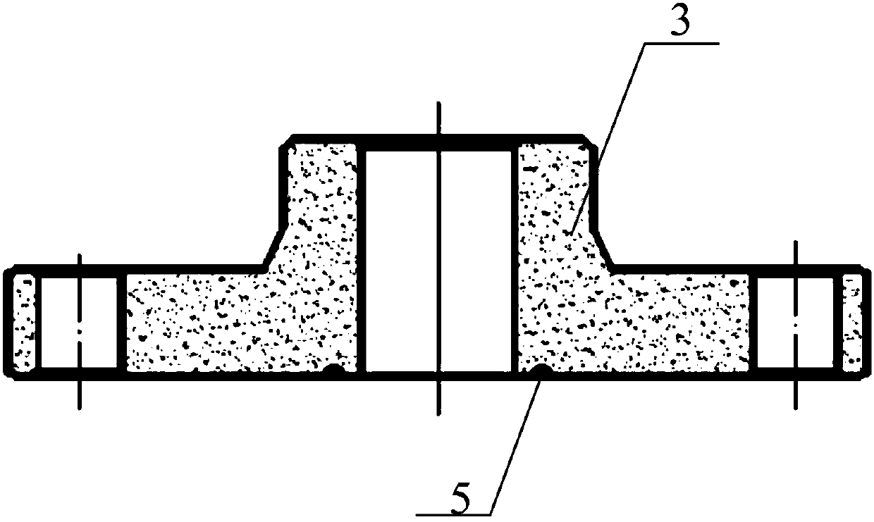
Cooperating structure of a rotor compressor and its crankshaft thrust surface and flange surface

A technology of rotor compressor and matching structure, which is applied in the field of compressor manufacturing, and can solve problems such as increased compressor power consumption, reduced crankshaft positioning accuracy, and wear on the thrust surface and flange surface of the crankshaft.

Active Publication Date: 2018-10-19
GREE ELECTRIC APPLIANCES INC +1
View PDF6 Cites 0 Cited by
  • Summary
  • Abstract
  • Description
  • Claims
  • Application Information

AI Technical Summary

Problems solved by technology

[0003] In the process of actual operation, the crankshaft is a moving part, but the flange that constitutes the compressor cylinder is a stationary part, so there is always sliding friction between the thrust surface of the crankshaft and the flange surface, which leads to the friction of the thrust surface of the crankshaft. The wear of the flange surface reduces the positioning accuracy of the crankshaft, and the sliding friction resistance at this position is relatively large, which increases the power consumption of the compressor

Method used


Image

  • Cooperating structure of a rotor compressor and its crankshaft thrust surface and flange surface
  • Cooperating structure of a rotor compressor and its crankshaft thrust surface and flange surface
  • Cooperating structure of a rotor compressor and its crankshaft thrust surface and flange surface

Examples


Embodiment Construction

[0021] One of the cores of the present invention is to provide a matching structure between the crankshaft thrust surface and the flange surface of the rotor compressor, so as to reduce the wear speed of the crankshaft thrust surface and the flange surface and reduce the power consumption of the compressor.

[0022] Another core of the present invention is to provide a rotary compressor using the above matching structure.

[0023] In order to enable those skilled in the art to better understand the solution of the present invention, the present invention will be further described in detail below in conjunction with the accompanying drawings and specific embodiments.

[0024] In the embodiment of the present invention, the thrust surface of the crankshaft and the flange surface having a friction fit relationship in a single-cylinder vertical compressor are used as an example to describe the cooperation structure between the thrust surface of the crankshaft and the flange surface...


PUM


Abstract

The invention relates to a matching structure of a crankshaft thrust surface and a flange surface of a rotor compressor. One of the crankshaft thrust surface and the flange surface is provided with multiple ball sockets distributed at intervals and positioned in the same one circle, and each ball socket is embedded with a ball; the other one is provided with an annular groove corresponding to the circle of the ball sockets for operating the balls; and a rotating center of a crankshaft penetrates through the circle center of the circle of the ball sockets. After the matching structure is adopted, and when the crankshaft and a flange relatively rotate, the sliding friction of the two is changed to rolling friction, so that the friction resistance and the wear speed of the contact positions of the two are largely reduced; on the one hand, the power consumption of the compressor is reduced; and on the other hand, the service life of the compressor is prolonged. The invention further discloses the rotor compressor adopting the matching structure.

Description

technical field [0001] The invention relates to the technical field of compressor manufacturing, in particular to a rotor compressor and a matching structure between a crankshaft thrust surface and a flange surface thereof. Background technique [0002] At present, the rotor compressor generally drives the crankshaft through the motor, and the crankshaft drives the rotor to rotate in the cylinder to realize the process of suction, compression and exhaust. Each cylinder is composed of two opposite flanges. It is customary in the industry to name the cylinder as the upper flange and the lower flange. Of course, they can also be collectively referred to as flanges. It is realized by the cooperation of the push surface and the flange surface. [0003] In the process of actual operation, the crankshaft is a moving part, but the flange that constitutes the compressor cylinder is a stationary part, so there is always sliding friction between the thrust surface of the crankshaft an...

Claims


Application Information

Patent Timeline
Patent Type & Authority Patents(China)
IPC IPC(8): F04C29/00
CPCF04C29/00F04C2240/601F04C2240/80
Inventor 樊峰刚魏会军赵旭敏彭慧明韩鑫卢林高曹彭杰
Owner GREE ELECTRIC APPLIANCES INC
Learn More