An array substrate row driving circuit

A technology of array substrate rows and drive circuits, which is applied to instruments, static indicators, etc., can solve problems such as signal delay, achieve the effect of solving time delay and improving display quality

Active Publication Date: 2018-03-27
TCL CHINA STAR OPTOELECTRONICS TECH CO LTD
View PDF5 Cites 0 Cited by
  • Summary
  • Abstract
  • Description
  • Claims
  • Application Information

AI Technical Summary

Problems solved by technology

[0005] The purpose of the present invention is to provide an array substrate row driving circuit to solve the signal delay problem caused by the capacitor directly connected to the horizontal scanning line in the prior art

Method used


Image

  • An array substrate row driving circuit
  • An array substrate row driving circuit
  • An array substrate row driving circuit

Examples


Embodiment Construction

[0033] The following descriptions of the various embodiments refer to the accompanying drawings to illustrate specific embodiments in which the present invention can be practiced. The directional terms mentioned in the present invention, such as "up", "down", "front", "back", "left", "right", "inside", "outside", "side", etc., are for reference only The orientation of the attached schema. Therefore, the directional terms used are used to illustrate and understand the present invention, but not to limit the present invention.

[0034] In the figures, structurally similar units are denoted by the same reference numerals.

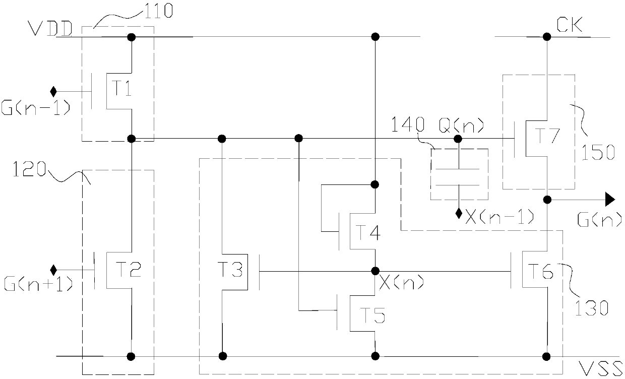
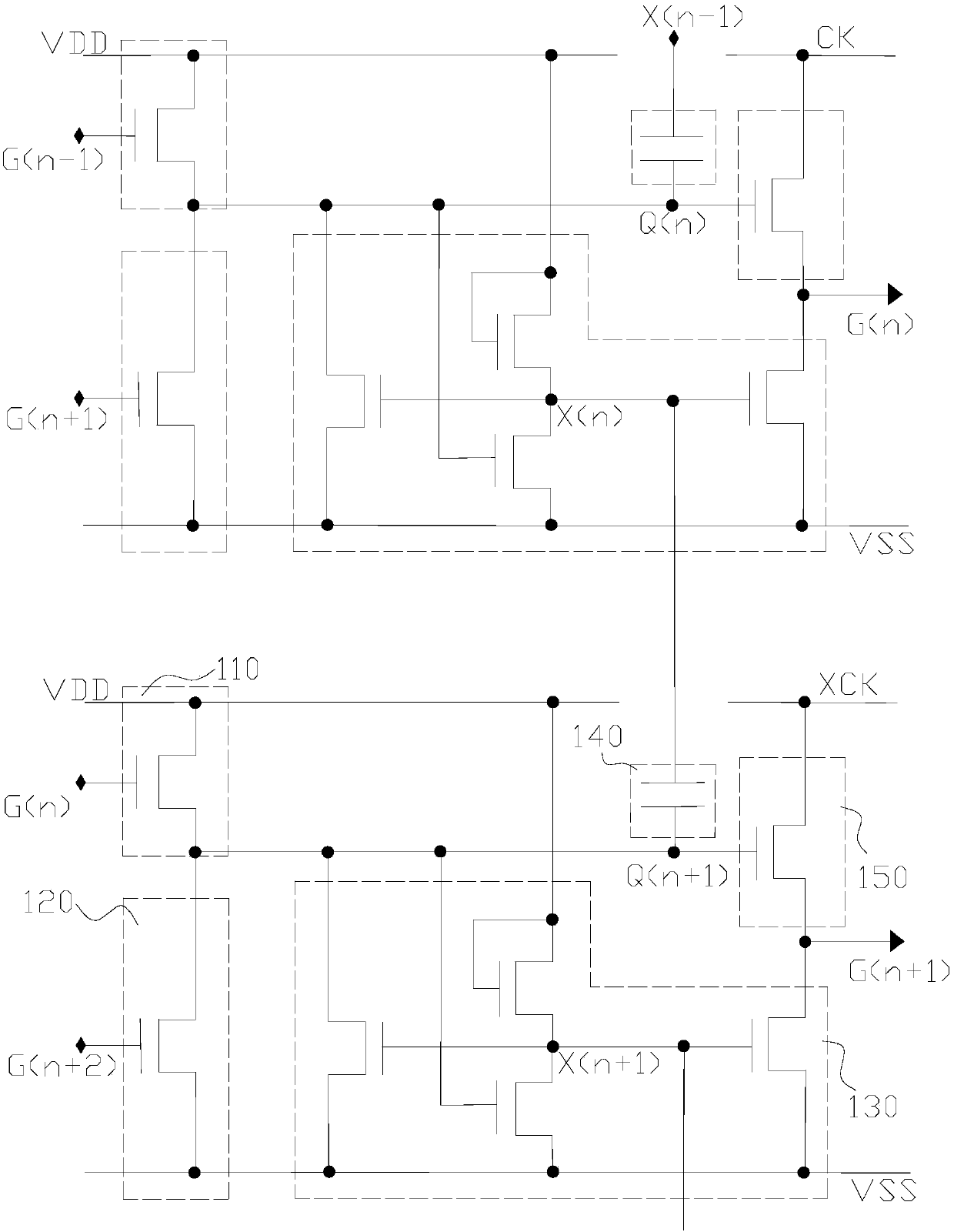
[0035] The array substrate row driving circuit provided by the present invention includes a plurality of cascaded array substrate row driving units, and each array substrate row driving unit is used to charge the corresponding horizontal scanning line, except for the zeroth array substrate row driving unit , the structures of the row driving units of the arr...


PUM


Abstract

The invention provides an array substrate row driving circuit, which comprises a plurality of cascaded array substrate row driving units. The nth array substrate row driving unit comprises a pull-up circuit, a pull-down circuit, a pull-down holding circuit, a capacitive circuit and an output circuit, wherein the capacitive circuit is respectively connected with a grid signal point and a pull-down holding circuit of the (n-1)th array substrate row driving unit and used for controlling the potential o the grid signal point according to potential variations of the pull-down holding circuit of the (n-1)th array substrate row driving unit. The array substrate row driving circuit provided by the invention can reduce the time delay of horizontal scanning line signals under the premise of not increasing the number of devices and not changing the potential waveform of the grid signal point, and greatly improves the display quality of a liquid crystal display.

Description

technical field [0001] The invention relates to the technical field of liquid crystal display, in particular to an array substrate row driving circuit. Background technique [0002] The GOA (Gate-driver On Array) technology, that is, the row-driven technology of the array substrate, is widely used in the display panel because it can save the cost of the Gate IC, reduce the width of the panel boundary, and the like. The existing array substrate row drive circuit is formed by cascading n array substrate row drive units. A capacitor is provided in each array substrate row drive unit. One end of the capacitor is connected to the gate signal point, and the other end Connected to the horizontal scanning line corresponding to the row driving unit of the array substrate, the capacitor is used to increase the potential of the gate signal point, so that the row driving unit of the array substrate is in an open and output state. [0003] However, since the capacitor is directly connec...

Claims


Application Information

Patent Timeline
Patent Type & Authority Patents(China)
IPC IPC(8): G09G3/36
CPCG09G3/3677
Inventor 杜鹏
Owner TCL CHINA STAR OPTOELECTRONICS TECH CO LTD
Why Eureka
Try Eureka