Method, apparatus and robotic system for moving an object to a target location

A target position and object movement technology, applied in the field of robot systems, can solve the problems of lack of effective methods and devices for moving to the target position, insufficient to meet the accuracy requirements of robot systems, etc., and achieve the effect of improving pose accuracy

Active Publication Date: 2018-02-06
ABB (SCHWEIZ) AG
View PDF5 Cites 0 Cited by
  • Summary
  • Abstract
  • Description
  • Claims
  • Application Information

AI Technical Summary

Problems solved by technology

However, this improvement is not enough to meet the precision requirements of robotic systems such as assembly systems
[0004] From the above it can be seen that there is a lack of efficient methods and devices for robotic systems to move objects to target locations with high precision

Method used


Image

  • Method, apparatus and robotic system for moving an object to a target location
  • Method, apparatus and robotic system for moving an object to a target location
  • Method, apparatus and robotic system for moving an object to a target location

Examples


Embodiment Construction

[0034] Some preferred embodiments will be described in more detail with reference to the accompanying drawings, in which preferred embodiments of the present disclosure are shown. However, the present disclosure can be implemented in various ways and thus should not be construed as being limited to the embodiments disclosed herein. Rather, these embodiments are provided so that this disclosure will be thorough and complete, and will fully convey the scope of this disclosure to those skilled in the art.

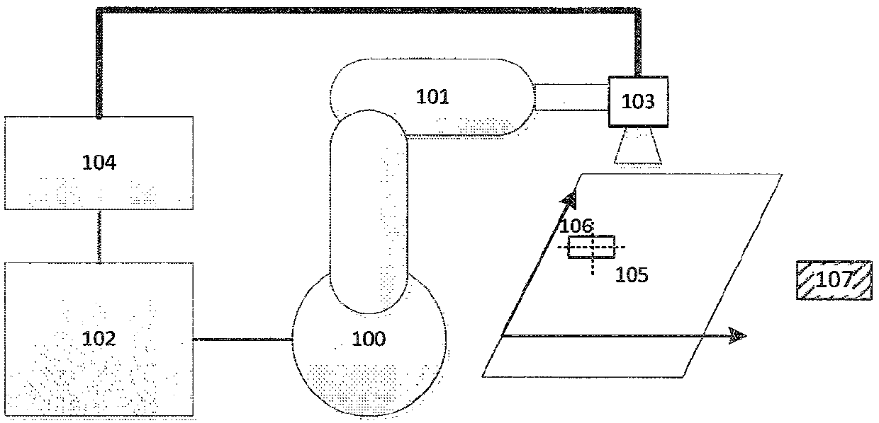
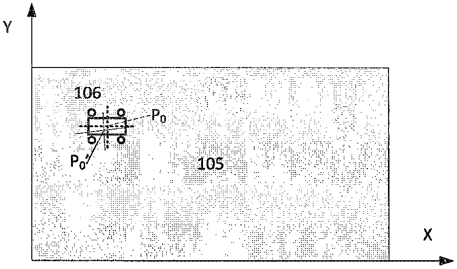
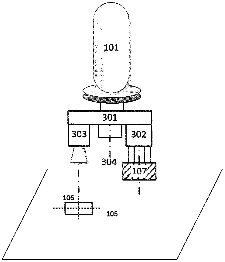
[0035] First refer to figure 1 , which schematically illustrates an exemplary layout of a vision-guided robotic system that may implement embodiments of the present disclosure. Such as figure 1 As shown, the robotic system may include a robot 100 , a control unit 102 and a vision system 104 . The robot 100 includes at least one arm 101 which may (or may not) hold a camera 103 to capture images of a target location 106 on a PCB board 105 where an object 107 should be placed....


PUM


Abstract

A method of moving an object to a target position by an industrial robot is provided, wherein the robot includes at least one arm and an actuator unit mounted at an end of the at least one arm. The method includes causing the robot to pick up an object at a first location via an actuator unit and moving the picked object to a second location; and causing the robot to pass through the actuator unit in response to a deviation between the second location and a target location. Motion correction bias.

Description

technical field [0001] Embodiments of the present disclosure relate to industrial robotic systems, and in particular, to methods, devices, and robotic systems for moving objects to target locations. Background technique [0002] With the development of robotics, automatic handling by picking up objects and moving them to target locations by industrial robots is widely used in various scenarios. The robot picks up the object at the first station and moves it to the second station for subsequent actions, such as placing it on a conveyor or performing assembly tasks, etc. However, the main problem with automatic processing is that the precision of the robot cannot meet the requirements of the system. This problem is especially prominent for assembly robots. For example, this type of system requires very high precision to assemble, eg <0.05mm. However, generally speaking, the absolute accuracy in the robot coordinate system may be 0.5-1.0 mm in the overall workspace, which...

Claims


Application Information

Patent Timeline
Patent Type & Authority Patents(China)
IPC IPC(8): B25J13/00
CPCB25J9/1697B25J9/1687G05B2219/36195G05B2219/40584G05B2219/40609
Inventor 孔鹏
Owner ABB (SCHWEIZ) AG
Why Eureka
Try Eureka