
Anti-shake device of mobile robotic vision system and anti-shake compensation control method therefor

A mobile robot and vision system technology, applied in manipulators, manufacturing tools, etc., can solve the problems of active compensation and control of mobile robot jitter, high frequency, and unclear image of vision device jitter.

Active Publication Date: 2012-03-28
HARBIN INST OF TECH
View PDF0 Cites 0 Cited by
  • Summary
  • Abstract
  • Description
  • Claims
  • Application Information

AI Technical Summary

Problems solved by technology

The disadvantage of this invention is that the correction is started after the dithering image comes out, and the effect of outputting a clear image at one time cannot be achieved.
The applicable conditions of this device are relatively stable panning conditions, and it is difficult to apply to the complex and irregular shaking environment faced by mobile robots
Civilian cameras and camera internal shake systems can only compensate for low-frequency and small shakes, while vision systems for wheeled, tracked, and legged mobile robots are all industrial vision camera devices, and there is no shake inside and outside the device Measures, while mobile robots with industrial vision systems move on uneven ground or in the field due to vibrations that cause the vision device to vibrate and the image is not clear. The jitter from the ground may be medium and low frequency, and there are also high frequency cases
Moreover, the vibration amplitude varies from small to large. Therefore, none of the anti-shake methods mentioned in the above-mentioned patents can solve the problem of active compensation and control of complex and irregular vibrations of mobile robots on uneven roads or in wild environments.

Method used


Image

  • Anti-shake device of mobile robotic vision system and anti-shake compensation control method therefor
  • Anti-shake device of mobile robotic vision system and anti-shake compensation control method therefor
  • Anti-shake device of mobile robotic vision system and anti-shake compensation control method therefor

Examples


specific Embodiment approach 1

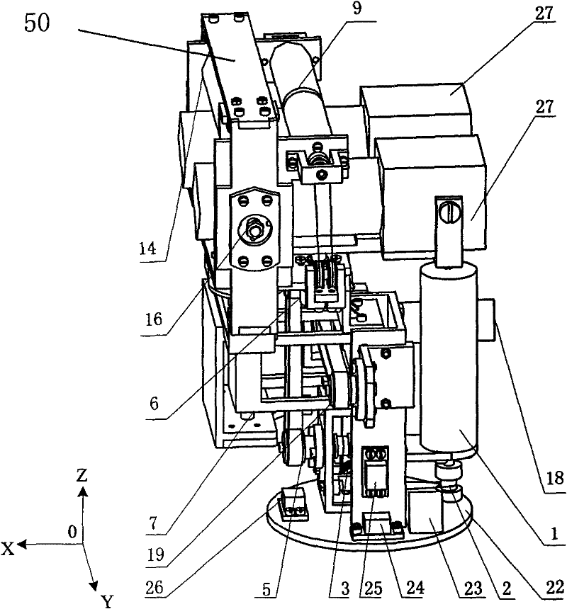
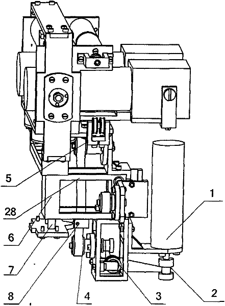
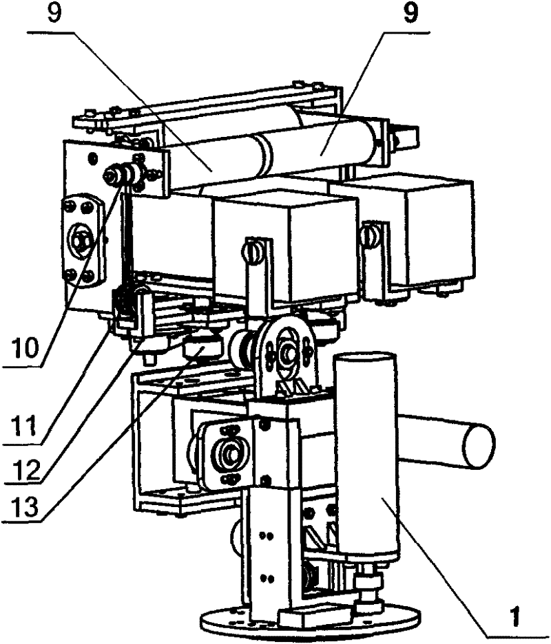
[0026] Specific implementation mode one, the following combination Figure 1a-1f , figure 2 Description of this embodiment: the mobile robot vision system anti-shake device described in this embodiment is composed of three parts: an anti-shake mechanism, a sensor system and an anti-shake control system; , a yaw unit and a base 22, the up and down movement unit, the left and right movement unit, the pitch unit and the yaw unit are all arranged on the base 22; the sensor system includes an inclination sensor 26, a first vibration sensor 24 and a second vibration sensor Sensor 25, tilt sensor 26, the first vibration sensor 24 and the second vibration sensor 25 are all installed on the base 22, and the tilt sensor 26 measures the rotation angle of the base 22 relative to the X-axis direction and the Y-axis direction respectively; the first vibration sensor 24 , The second vibration sensor 25 measures the movement of the base 22 along the Z-axis direction and the Y-axis direction...

specific Embodiment approach 2

[0035] Specific embodiment two, combine image 3 , Figure 4 , Figure 5 , Image 6 Describe this embodiment, the anti-shake compensation control method of the mobile robot vision system anti-shake device described in this embodiment is:

[0036] Step 1, the shaking parameter h measured by the first vibration sensor 24, the second vibration sensor 25 and the inclination sensor 26 1 、h 2 , and the corresponding difference to determine the velocity and acceleration of the measured jitter change;

[0037] Step 2. According to the situation measured by the sensor system within the sampling time T, it is judged whether there is jitter in the vision system of the mobile robot; if jitter needs to be compensated, perform step 3; otherwise, no compensation is required;

[0038] Step 3. Calculate the compensation amount: establish the D-H coordinate system of each kinematic joint to describe the translation between adjacent rods a 1 、a 2 and rotate θ 3 , θ 4 , θ 5 The relati...

specific Embodiment approach 3

[0050] Specific implementation mode three, the following combination Figure 7 To illustrate this embodiment, the vision system anti-shake device of the present invention can be applied to a humanoid robot 30 . The vision system anti-shake device can be used as the head of the humanoid robot, and is fixedly connected with the interface on the neck 31 of the humanoid robot 30 through the device base 22 . The anti-shake control system 23 in the anti-shake device of the vision system is used as the bottom control system of the anti-shake control, and is connected with the upper control machine in the chest of the humanoid robot 30 through a control line and a data line.


PUM


Abstract

The invention discloses an anti-shake device of a mobile robotic vision system and an anti-shake compensation control method therefor, and relates to an anti-shake device of a vision system for a robot and an anti-shake compensation control method. Aiming at the shake of a mobile robot, machinery and control methods are used to fundamentally eliminate the shake of the robotic vision system in real time; therefore, the stable motion of the vision system can be achieved. The vision system anti-shake device comprises an anti-shake mechanism, a sensor system and an anti-shake control system whichis used for realizing the anti-shake of the vision system. The method has the following steps: measuring the shake parameters, judging whether the mobile robotic vision system shakes or not, calculating the compensation amount, planning compensation track, giving feedback based on PD, calculating shake compensation control by the reverse dynamics The anti-shake device realizes the motion control of two vision sensors within a large range, and prevents and controls the shake generated by the two vision sensors. With the anti-shake compensation control method adopted, each pose parametric curveof the two vision sensors can accurately be close to the expected pose parametric curve.

Description

technical field [0001] The invention relates to an anti-shake device and an anti-shake compensation control method for a robot vision system, belonging to the field of robot applications. Background technique [0002] Robot vision is a new and rapidly developing subject. Since the 1980s, the research of robot vision has gone through the development stage from laboratory to practical application. But at the same time, there are many problems in the robot vision system. During the moving process of the robot, it often encounters uneven road shaking, and the images captured by its vision system cannot avoid motion blur. [0003] For the problem of motion blur, generally using a higher shutter speed can reduce the photo blur caused by this kind of vibration, but in shooting with a long exposure time, such as in cloudy days or in the evening, the pictures taken are relatively blurry, which is Due to the relatively long shutter time in the low-light environment, in this case, th...

Claims


Application Information

Patent Timeline
Patent Type & Authority Patents(China)
IPC IPC(8): B25J5/00B25J19/00
Inventor 吴伟国邵益凯
Owner HARBIN INST OF TECH
Learn More