Excavator arm movement control method, system and device

A motion control and excavator technology, which is applied in the fields of earthmoving machines/shovels, construction, etc., can solve the hidden danger of casualties, and the autonomous motion control scheme of the excavator arm has not been proposed, so as to achieve the goal of reducing labor costs and efficient operation. Effect

Inactive Publication Date: 2019-02-01
北京拓疆者智能科技有限公司
View PDF5 Cites 7 Cited by
  • Summary
  • Abstract
  • Description
  • Claims
  • Application Information

AI Technical Summary

Problems solved by technology

Excavators have been widely used in mines, building demolition, tunnel excavation and other scenarios. Since most excavator arms are in the manual control stage, there are hidden dangers of casualties in some high-risk operation scenarios. At present, no better excavator arms have been proposed. autonomous motion control scheme

Method used


Image

  • Excavator arm movement control method, system and device
  • Excavator arm movement control method, system and device
  • Excavator arm movement control method, system and device

Examples


Embodiment 1

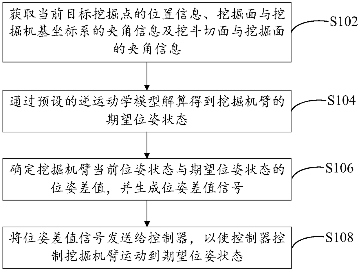
[0032] Embodiment 1 of the present invention provides an excavator arm motion control method, see figure 1 The flow chart of the excavator arm motion control method is shown, the method includes the following steps:

[0033] Step S102, obtaining the position information of the current target excavation point, the angle information between the excavation surface and the base coordinate system of the excavator, and the angle information between the cutting surface of the bucket and the excavation surface;

[0034] The current target excavation point refers to the point to be excavated by the excavator, that is, the contact point between the bucket tooth tip of the excavator and the surface to be excavated. The base coordinate system is a coordinate system established based on the plane where the excavator is located. The position information of the current target excavation point refers to the coordinate information of the current target excavation point in the base coordinate ...

Embodiment 2

[0079] Embodiment 2 of the present invention provides an excavator arm motion control system, see Figure 4 The structural block diagram of the excavator arm motion control system shown, the system includes:

[0080] The expected signal acquisition module, the controller module, the signal conversion module, the error calculation module and the sensor module; the expected signal acquisition module is used to obtain the position information of the current target excavation point, the angle information between the excavation surface and the base coordinate system of the excavator, and the bucket The angle information between the cutting surface and the excavation surface generates the expected pose state of the excavator arm; the expected signal acquisition module is also used to determine the pose difference between the current pose state and the expected pose state of the excavator arm, and generates The pose difference signal of the excavator arm, and send the pose difference...

Embodiment 3

[0082] Embodiment 3 of the present invention provides an excavator arm motion control device, see Figure 5 The structural block diagram of the excavator arm motion control device shown, the device includes:

[0083] The information acquisition module 51 is used to obtain the position information of the current target excavation point, the angle information between the excavation surface and the base coordinate system of the excavator, and the angle information between the bucket cut surface and the excavation surface; The inverse kinematics model of the excavator arm is calculated to obtain the expected pose state of the excavator; the difference module 53 is used to determine the pose difference between the current pose state and the expected pose state of the excavator arm, and generate a pose difference signal ; The sending module 54 is used to send the pose difference signal to the controller, so that the controller controls the movement of the excavator arm to a desired ...


PUM


Abstract

The invention provides an excavator arm movement control method, system and device and relates to the technical field of automatic control. The excavator arm movement control method comprises the steps of acquiring the position information of a current target excavation point, the included angle information of an excavation face and excavator based coordinate system and the information of an included angle between an excavator bucket section and the excavation face; carrying out resolution through a preset inverse kinematics model to obtain the expected pose state of an excavator arm, determining the pose difference between the current pose state and the expected pose state of the excavator arm, and generating a pose difference signal; and sending the pose difference signal to a controller, and using the controller to control the excavator arm to move to the expected pose state. The excavator arm movement control method, system and device can achieve movement control over the excavatorarm, thereby achieving stable and efficient operation of the excavator arm and lowering the labor cost.

Description

technical field [0001] The invention relates to the technical field of automatic control, in particular to an excavator arm motion control method, system and device. Background technique [0002] An excavator is an earth-moving machine that uses a bucket to excavate materials above or below the bearing surface and loads them into transport vehicles or unloads them to the stockyard. The materials excavated by the excavator are mainly soil, coal, sediment, and pre-loose soil and rock. Excavators have been widely used in mines, building demolition, tunnel excavation and other scenarios. Since most excavator arms are in the manual control stage, there are hidden dangers of casualties in some high-risk operation scenarios. At present, no better excavator arms have been proposed. autonomous motion control scheme. Contents of the invention [0003] In view of this, the object of the present invention is to provide an excavator arm movement control method, system and device to c...

Claims


Application Information

Patent Timeline
Patent Type & Authority Applications(China)
IPC IPC(8): E02F9/14E02F9/20
CPCE02F9/14E02F9/2037
Inventor 卢兴阳隋少龙张越
Owner 北京拓疆者智能科技有限公司
Why Eureka
Try Eureka